Monopulse azimuth radar system for automotive vehicle tracking

a radar system and vehicle tracking technology, applied in the field of vehicular collision avoidance radar systems, can solve problems such as demultiplexing of signals

Inactive Publication Date: 2000-08-15
BENDIX COMML VEHICLE SYST LLC
View PDF8 Cites 32 Cited by
  • Summary
  • Abstract
  • Description
  • Claims
  • Application Information

AI Technical Summary

Benefits of technology

The system employs a monopulse antenna designed to provide a tracking beam width of limited and controllable size. In this way, vehicles in the same lane as the vehicle on which the system is mounted or even in an adjacent lane can be identified, distinguished, and tracked, both over straight stretches of highway and around curves, to the exclusion of other potential targets, such as vehicles having an angular displacement greater than a specified angular displacement measured from the reference azimuth.

Problems solved by technology

A switch coupled within the two channels may be employed to switch between two frequencies of the source signal, thus demultiplexing the signal.

Method used


Image

  • Monopulse azimuth radar system for automotive vehicle tracking
  • Monopulse azimuth radar system for automotive vehicle tracking
  • Monopulse azimuth radar system for automotive vehicle tracking

Examples


Embodiment Construction

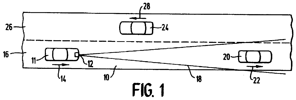
FIG. 1 shows a portion of a roadway 10 which has a vehicle 11 thereon equipped with a monopulse radar system 12 according to the present invention. The vehicle 11 travels in a direction shown by an arrow 14 within a lane 16 of the roadway 10. The monopulse radar system 12 of the vehicle 11 transmits a radar beam 18 extending from the front end of the vehicle 11 where the monopulse radar system 12 is mounted. The radar beam 18 is shown as encompassing a tracked vehicle 20. The tracked vehicle 20 is moving in the same direction as the vehicle 11, as represented by an arrow 22, within the lane 16. A third vehicle 24 is shown in a second lane 26 of the roadway 10, and travelling in an opposite direction from the vehicles 11 and 20, as represented by an arrow 28.

Monopulse radar systems in accordance with the preferred embodiment of the present invention transmit a radar beam 18 which can be adjusted, and which is selected to track targets in the same travel lane as the vehicle on which t...


PUM


Abstract

A monopulse vehicular radar system for tracking a target about an automotive vehicle senses a transmitted signal reflected back from the target and received at two different locations, determines the sum and the difference of the reflected signals sensed at the two locations, and compares the sum and difference to determine the deviation of the target from a reference azimuth. A source frequency provided by a Gunn diode is applied to and transmitted by a two-lobe monopulse antenna. The antenna lobes detect the reflected signals from the target by sensing them at the two different lobes. A hybrid junction provides sum and difference signals to mixers which homodyne the signals to produce sum and difference Doppler frequency signals using the source frequency. The Doppler frequency signals are amplified and then compared to determine the deviation of the target from the reference azimuth. The comparison process can be done digitally by converting the amplified frequency signals to digital signals which are then processed in a digital signal processor, or the comparison may be done in analog fashion using a phase / quotient detector. The range or distance of the target is determined by shifting the source frequency between two frequencies during transmission and frequency shifting the sum and difference Doppler frequency signals in similar fashion following reception by the antenna.

Description

BACKGROUND OF THE INVENTION1. Field of the InventionThis invention relates to vehicular radar systems, and more particularly to a vehicular collision avoidance radar system which tracks a target within a narrowed radar beamwidth.2. Description of the Prior ArtThere is a continuing need to increase the density of vehicles traveling the world's roadways and simultaneously to improve the safety of highway vehicle operations by preventing highway vehicles from colliding with stationary and moving objects (such as roadside obstacles and other vehicles). One means for accomplishing these seemingly contradictory goals is to monitor the relative speed, direction of travel, and distance between vehicles sharing the roadway, and to use such information to provide direct indications to the vehicle's operator of potential danger. It is becoming increasingly more common for automotive engineers to consider the use of microwave radar systems as a means to monitor such environmental conditions.Veh...

Claims


Application Information

Patent Timeline
Patent Type & Authority Patents(United States)
IPC IPC(8): G01S13/93G01S13/00G01S13/34G01S13/72G01S13/44G01S7/40G01S13/931
CPCG01S13/348G01S13/44G01S13/72G01S13/931G01S7/4004G01S2013/9375G01S2013/93271G01S13/88
Inventor GELLNER, ROBERT C.WOLL, BRYAN D.WOLL, JERRY D.DAVIS, JOHN W.TUBBS, DUANE G.
Owner BENDIX COMML VEHICLE SYST LLC
Why Eureka
Try Eureka