Layable seat

Inactive Publication Date: 2001-02-06
KOTOBUKI & CO LTD
View PDF13 Cites 17 Cited by
  • Summary
  • Abstract
  • Description
  • Claims
  • Application Information

AI Technical Summary

Benefits of technology

The present invention has been derived from the above situation, and its object is to provide a layable seat which can hold a seat member at a half-folded position between a horizontal use position and a vertically folded position before a user sits down while the layable seat is set at a raised use position, so that the user can move the seat member to the horizontal use position with his or her buttocks without using his or her hand,

Problems solved by technology

For this reason, every time the front end of the seat member abuts against the upper surface of the corresponding deck, comparatively large noise is produced.
The front end of the seat member, and a portion of the upper surface against

Method used


Image

  • Layable seat
  • Layable seat
  • Layable seat

Examples


Embodiment Construction

A layable seat according to an embodiment of the present invention will be described in detail with reference to the accompanying drawings.

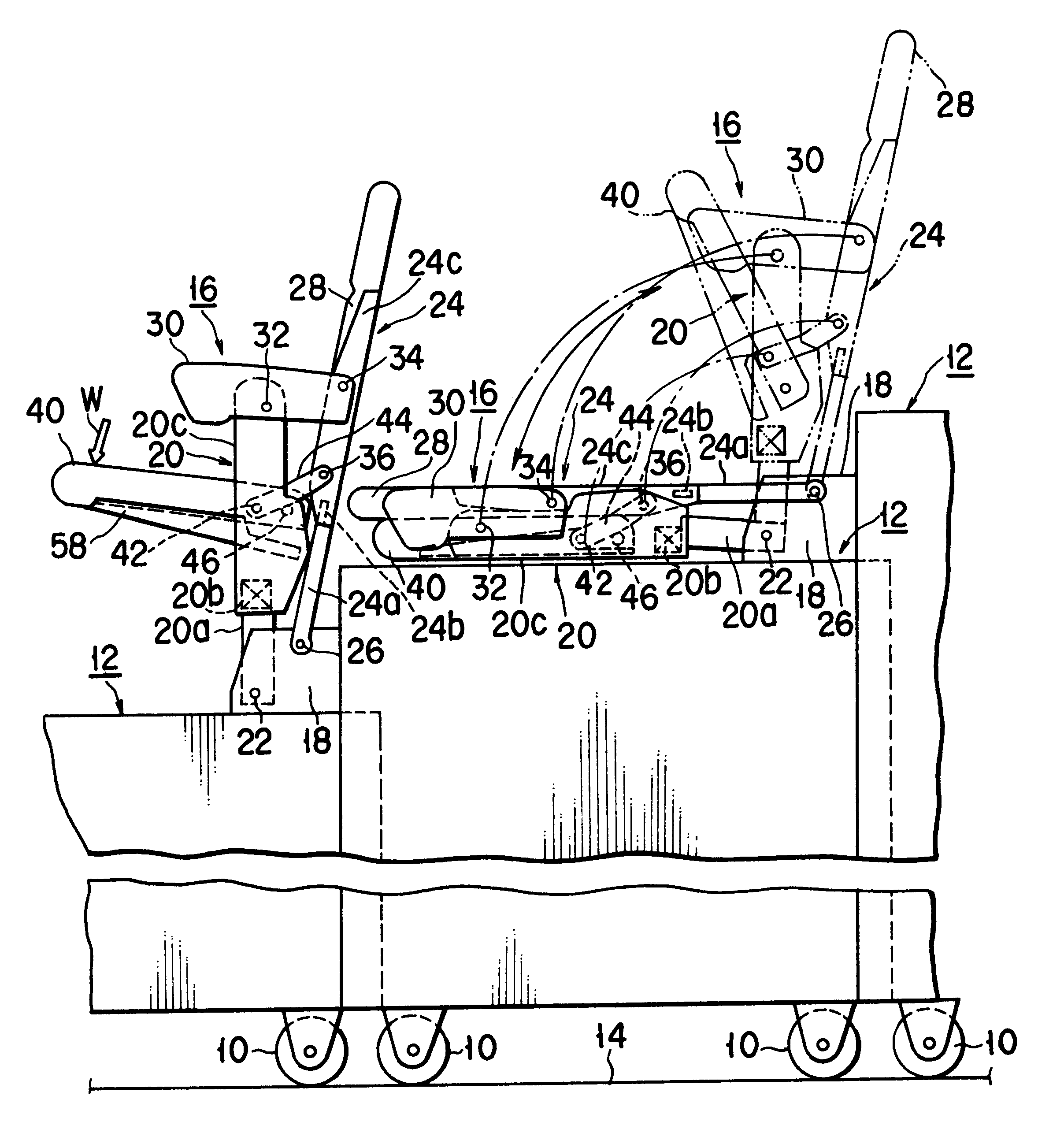
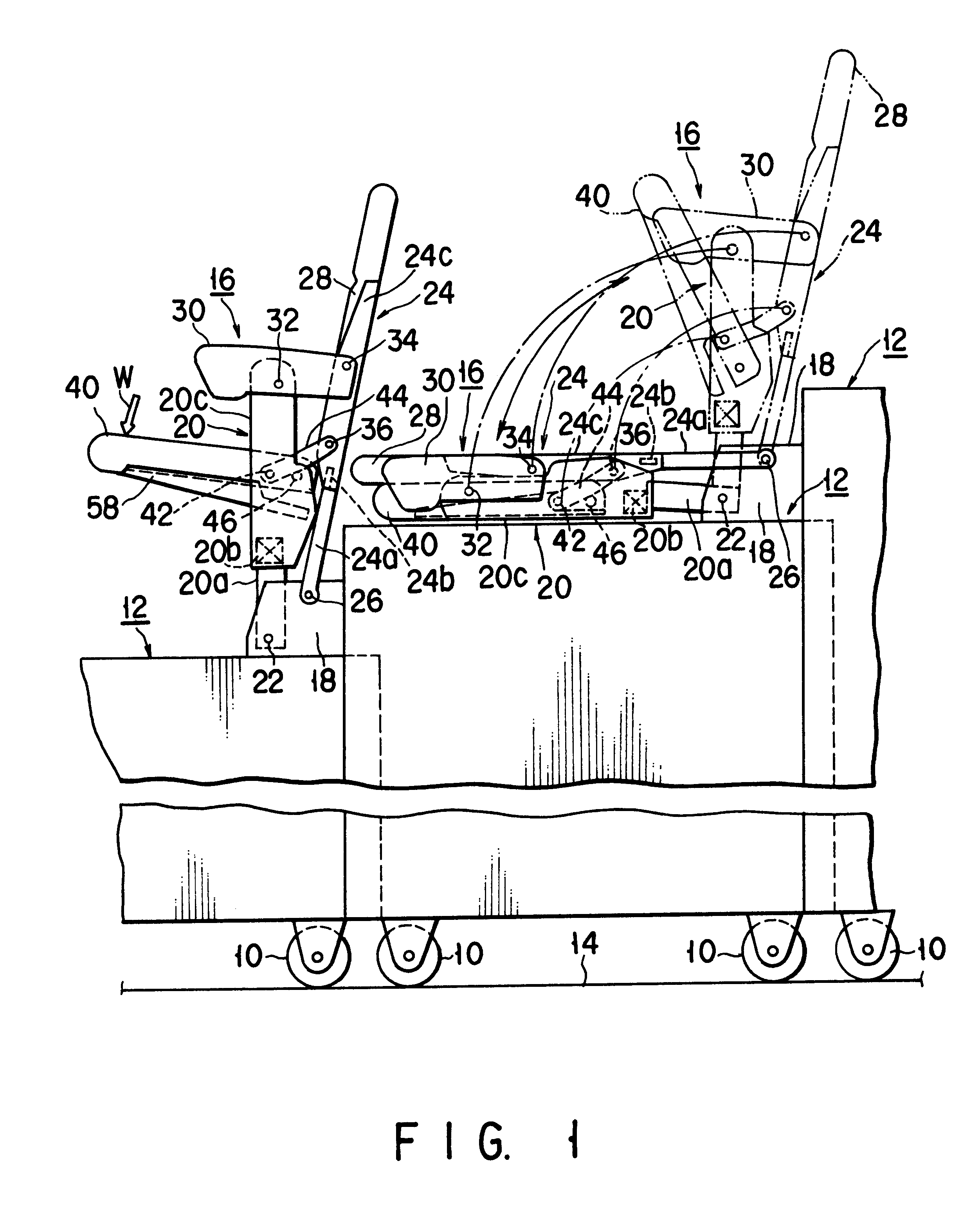
FIG. 1 shows a plurality of nestable movable decks 12. The movable decks 12 have sequentially different heights, and a plurality of wheels 10 serving as traveling means are provided at a lower end portion of each movable deck 12. The plurality of nestable movable decks 12 can be moved on a floor surface 14 of, e.g., a gymnasium, a community center, or a multi-purpose hall by the plurality of wheels 10 at their lower end portions.

The plurality of nestable movable decks 12 can extend telescopically on the floor surface 14 as shown in FIG. 1, and the decks lower than the highest deck are sequentially nested in the inner space of the highest deck. A gap having a predetermined height is defined between the top plates of the adjacent two nestable movable decks 12.

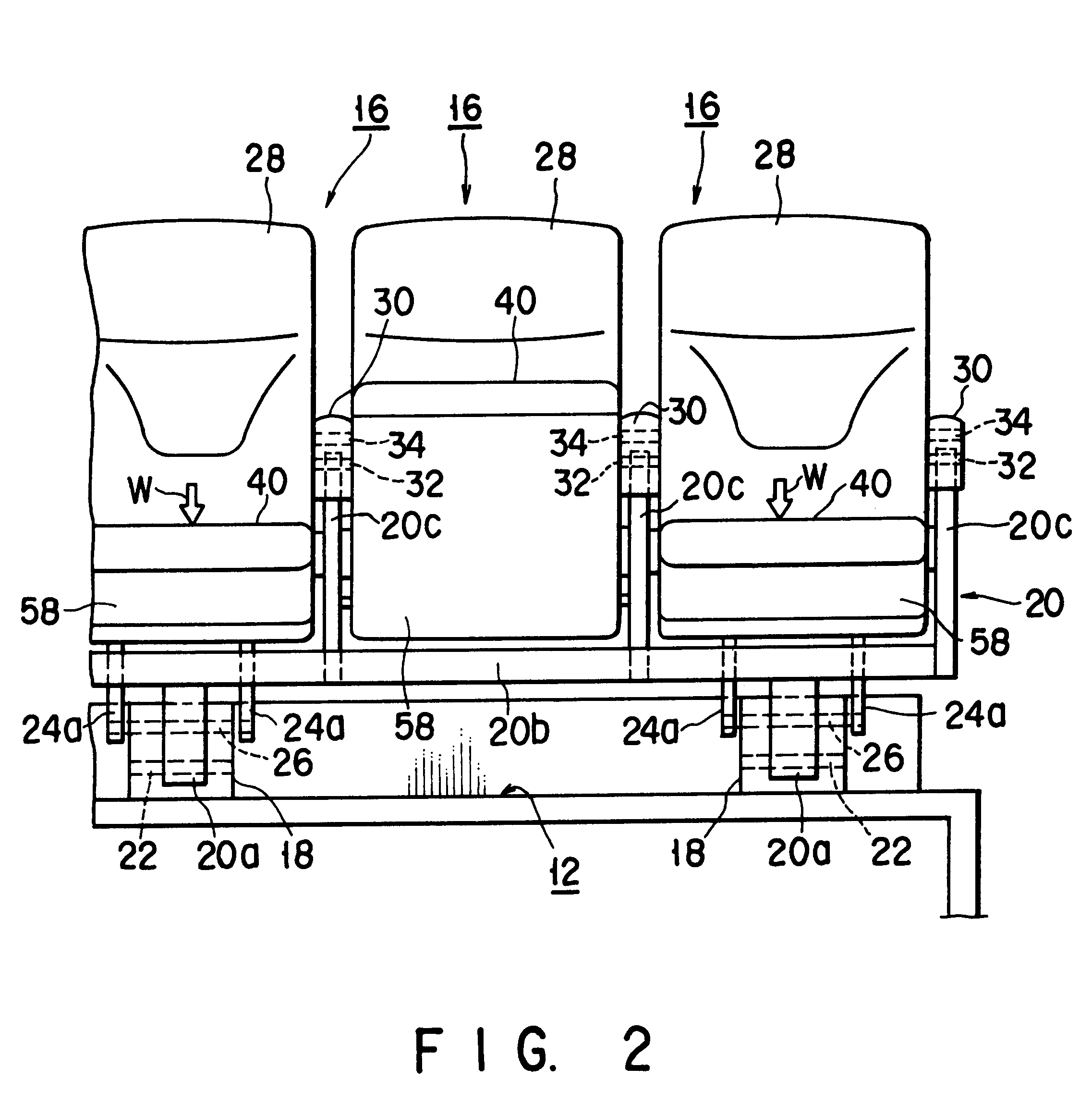
A plurality of layable seats 16 according to the embodiment of the present invention are i...


PUM


Abstract

A layable seat includes front and rear paired supporting legs which are layably raised on a floor at two positions separated from each other in a back-and-forth direction, a seat member pivotably connected to the front paired legs, paired link levers each of which has one end pivotably connected to the corresponding one pivotal center of the seat member and the other end pivotably connected to the corresponding rear leg. The seat member is elastically held at its half-folded position by torsion coil springs, and has paired engaging pins which project sideward therefrom and engage the lower edges of the link levers to hold the seat member at its horizontal position against a user's weight.

Description

BACKGROUND OF THE INVENTION1. Field of the InventionThe present invention relates to a seat and, more particularly, to a layable seat which is entirely pivotal between a horizontally laid non-use position where the seat is laid horizontally along a floor surface, and a raised use position where the seat is raised from the floor.2. Description of the Related ArtThe layable seat described above is known from, e.g., Published Unexamined Japanese Patent Application No. 62-101211. Such a seat is set on the upper surface of each of a plurality of nestable decks, which are movably installed on the floor surface of, e.g., a gymnasium, a community center, or a multi-purpose hall, and have sequentially different heights. And, these seats are used to temporarily set seats or increase the number of seats.Each of the plurality of decks has a plurality of wheels at its lower end portion so that the deck is movable on the floor surface of the building as described above. The plurality of decks are...

Claims


Application Information

Patent Timeline
IPC IPC(8): A47C1/00A47C1/126E04H3/12
CPCA47C1/126
Inventor YAMAZAKI, RYOKICHI
Owner KOTOBUKI & CO LTD
Why Eureka
Try Eureka