Continuous conveyor

a conveyor and continuous technology, applied in the direction of conveyors, transportation and packaging, etc., can solve the problems of relatively complex structures and inability to lift pallets by operators, and achieve the effects of large angular coverage, cost-effectiveness, and simple implementation

Active Publication Date: 2017-09-12
BLEICHERT AUTOMATION
View PDF26 Cites 1 Cited by
  • Summary
  • Abstract
  • Description
  • Claims
  • Application Information

AI Technical Summary

Benefits of technology

[0008]The advantages of the invention can be seen in particular in the fact that at least one first form closure element or frictional closure element is fixed to the underside of the pallet, which, upon driving into the respective reversal section, comes into a form-locking or frictional-locking engagement with at least one second form closure element or frictional closure element arranged there, which rotates in the at least one reversal section and carries the pallet by means of a form closure or frictional closure. This form closure or frictional closure becomes disengaged once again upon driving out from the reversal section. As a result of the fixing on the pallet, the first form closure element or frictional closure element moves together with the pallet into the at least one reversal section; that is, it does not rotate around itself. According to the invention, the first and / or the second form closure element or frictional closure element is elastically yielding. For this purpose, the first and / or the second form closure element or frictional closure element features at least one elastic buffer component. If the two form closure elements or frictional closure elements hit each other, the first and / or the second form closure element or frictional closure element yields. As a result of the elastic yielding, at least one of the two form closure elements or frictional closure elements is pushed away from the other and slightly deviates, in order subsequently to be mounted closely to the other form closure element or frictional closure element—under a counter-pressure that is generated, for example, by forcibly guided rollers of the pallet. This allows a strong form closure or frictional closure between the two form closure elements or frictional closure elements. Depending on the geometrical arrangement of the form closure elements or frictional closure elements, at the beginning (that is, upon the initial interlocking of the two form closure elements or frictional closure elements), a relative movement of such elements relative to each other in the circulating direction of the pallet is caused by the elastic yielding, such that, in particular, the first form closure element or frictional closure element, and thus also the pallet, can slide into its final position, in order to achieve the desired form closure or frictional closure. Thus, if a collision between the front edge of the first form closure element or frictional closure element with the second form closure element or frictional closure element arises, a forced clamping by means of the elastic component, and thus mechanical damage to the parts involved, is avoided. The synchronization of the pallet movement with the tension elements is no longer necessary.
[0031]With all of the embodiments described, for the application of a counter-pressure for the realization of the form closure or frictional closure, it is advantageous if a slotted link, which is preferably semicircular, is provided on both sides on the reversal sections, along which the rollers of the pallet run. This ensures a simple and efficient guidance of the pallet rollers or pallet wheels in the reversal sections, which ensures the counter-pressure of the pallet against the second form closure element or frictional closure element. The actual carrying of the pallet is realized by the driven second form closure element or frictional closure element, on the basis of the form closure or frictional closure between the two form closure elements or frictional closure elements.

Problems solved by technology

However, with this structure, a simple lifting of the pallet by an operator is not possible.
However, such structures are relatively complex.

Method used


Image

  • Continuous conveyor
  • Continuous conveyor
  • Continuous conveyor

Examples


first embodiment

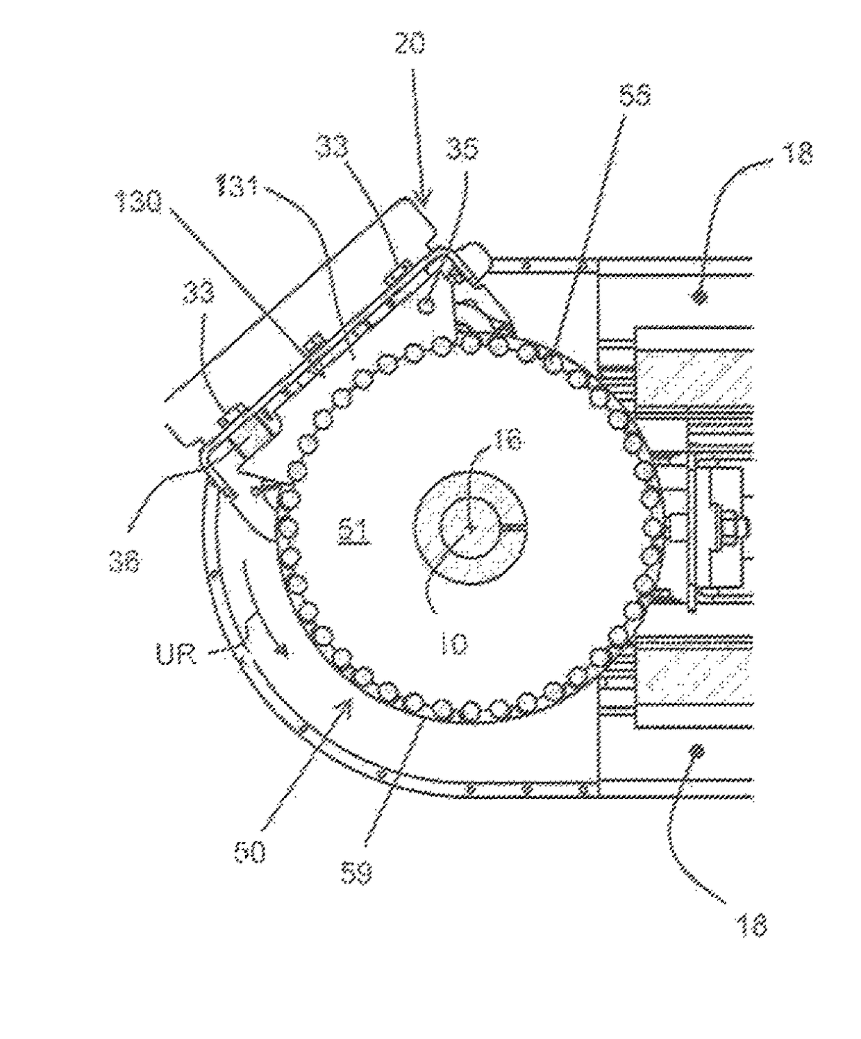
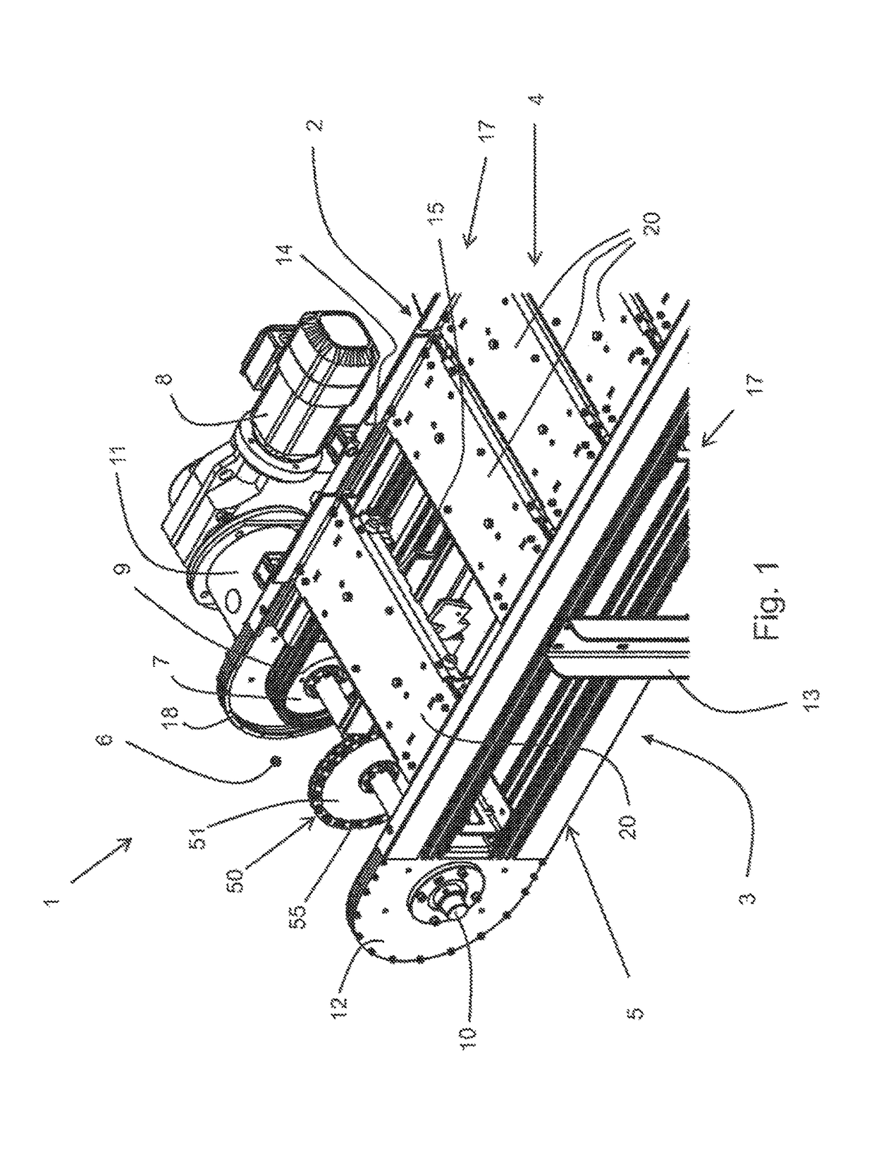
[0054]FIGS. 2-5 show a first form closure element or a frictional closure element 30. This is provided in the transverse center on the underside 22 of the pallet 20 and comprises a rigid component 31, which is formed to be elongated and extends in the circulating direction UR (see FIG. 3) of the pallet 20. The rigid component 31 features a toothed segment 40 with nine gear teeth 41, which form a concave envelope curve 39 (see FIG. 8) with a constant radius. Instead of nine gear teeth, toothed segments 40 with a different number of gear teeth 41, for example toothed segments 40 with three, six, eight or ten gear teeth 41, can also be used. In the present case, the nine gear teeth 41 extend across an angular range of approximately 70°. The connection to the underside 22 of the pallet 20 is effected by means of two cylindrical elastic buffer components 36, 37, whereas the buffer component 36 is arranged on the front side of the pallet 20 pointed towards the circulating direction UR, an...

third embodiment

[0063]FIGS. 9-11 show a first and second form closure element or frictional closure element 230, 250. With this embodiment, the first form closure element or frictional closure element 230 does not have elastic buffer components; rather; it solely comprises a rigid component 231, which is fastened (for example, welded) to the underside 22 of the pallet 20. The rigid component 231 features a toothed segment 40 that extends in the circulating direction UR and is directed away from the underside 22 of the pallet 20, and here also features nine gear teeth 41, the teeth peaks of which define an envelope curve 39 (see FIG. 11). The angular range a swept by the toothed segment 40 likewise amounts to approximately 65°.

[0064]According to the third embodiment, the second form closure element or frictional closure element 250 in the present case is not a gear wheel made of a solid material; rather, it features an inner rigid body 252 in the form of a disk with a smooth edge or a toothed rim, p...

fourth embodiment

[0066]FIGS. 12-14 show a fourth embodiment in which, in contrast to the preceding embodiments, a frictional closure is established between the first and second form closure elements or frictional closure elements 330, 350. For this purpose, the first form closure element or frictional closure element 330 is formed to be comparable to the first form closure element or frictional closure element 130 (elastic buffer component 36, deflection around the axis of rotation 35), with the difference that, instead of a toothed segment 40 on the rigid component 331, a uniform concave frictional surface 343 is provided, which in turns takes the form of an envelope curve 39 in the side view. The angular range a swept by the toothed segment 40 likewise amounts to approximately 65°. The second form closure element or frictional closure element 350 features a rigid body 352 with a convex frictional closure surface 353 that matches the concave frictional closure surface 343.

[0067]Upon the running agr...


PUM


Abstract

A closed continuous conveyor for pallets has an upper run and a lower run, which respectively form an upper and a lower conveyor track with reversal sections in which deflecting elements are arranged, of which at least one is connected to and driven by an engine, with tension elements rotating endlessly in the upper and lower runs and in the reversal sections, which engage the deflecting elements in the reversal sections and are driven by them. At least one rotating pallet is carried by the tension elements. At least one closure element is fixed to the underside of the pallet and engages in the reversal section with a second form closure element or frictional closure element that rotates around a fixed axis of rotation. The closure element includes at least one elastic buffer component.

Description

FIELD OF THE INVENTION[0001]The invention relates to a continuous conveyor that moves pallets along an elongated upper run at the end of which the pallets reverse direction and then proceed back along an elongated lower run parallel to the upper run.BACKGROUND OF THE INVENTION[0002]Such continuous conveyors have long been known. In the upper run, workpieces placed on the rotating pallets—also known as workpiece carriers—are transported from one location to another. The workpieces comprise, for example, mounting parts for motor vehicle production that are transported to an assembly line by means of pallets. On the assembly line, the workpieces are removed, for example, by a robot, and are processed by production machines. Generally stated, such continuous conveyors are provided at various points and for the most diverse applications.[0003]The tension elements are often designed as endless transport chains that rotate in the two side sections of the continuous conveyor. They are drive...

Claims


Application Information

Patent Timeline
Patent Type & Authority Patents(United States)
IPC IPC(8): B65G17/12B65G17/48B65G21/20B65G17/34B65G19/02B65G17/00B65G17/06
CPCB65G17/34B65G17/002B65G17/067B65G17/48B65G19/02B65G17/12
Inventor SCHIRLE, ANTONGRAAF, WOLFGANG
Owner BLEICHERT AUTOMATION
Why Eureka
Try Eureka