Assembly for gas turbine, associated gas turbine

a gas turbine and associated technology, applied in the field of turbines, can solve problems such as premature wear and impaired performance, and achieve the effect of limiting the wear of sealing plates

Active Publication Date: 2020-09-01
SN DETUDE & DE CONSTR DE MOTEURS DAVIATION S N E C M A
View PDF15 Cites 0 Cited by
  • Summary
  • Abstract
  • Description
  • Claims
  • Application Information

AI Technical Summary

Benefits of technology

[0012]The invention thus provides a solution allowing sealing in the gas turbine, whilst limiting sealing plate wear.
[0019]at least two projections extending from the second longitudinal face of the sealing plate, either side of a central longitudinal area of the sealing plate, where the height of each projection is chosen so as to reduce a clearance between the sealing plate and the first and second apertures, where the clearance is in range [0.1 mm, 0.5 mm],
[0023]Indeed, fitting the sealing plate between two adjacent parts of the gas turbine enables the space between said parts to be sealed, and thus gas leaks via said space to be prevented. In addition, the presence of the two projections enables the clearance between the sealing plate and the apertures to be reduced. More specifically, the height of the projections is chosen so as to minimise the clearance, in order to restrict the movement of the sealing plate when it is fitted in the apertures. It should be noted that the clearance must be sufficient to enable the sealing plate to be installed in the apertures of the parts. Limiting the sealing plate's movement and vibrations in the apertures means that the sealing plate and the parts of the gas turbine can no longer become worn prematurely, or become disengaged from the apertures, and thus damage other parts of the gas turbine. The maintenance operations and costs relating to the replacement of the parts of the gas turbine are therefore reduced.
[0024]Furthermore, the addition of such projections enables the clearance to be reduced, whilst limiting the mass of the sealing plate. Indeed, the use of projections enables the use of very thick sealing plates, which can reduce the turbomachine's performance, to be avoided. It is thus possible to use a thin sealing plate, and to add projections to it the height of which is adjusted depending on the desired clearance between the sealing plate and the apertures. The projections can be made in the sealing plate for example by a process of stamping or forming.
[0025]The assembly according to the invention is therefore a simple and inexpensive solution enabling a seal to be made between two adjacent parts of the turbomachine, whilst limiting the mass of said turbine.

Problems solved by technology

Indeed, the combined vibratory phenomena at high temperatures in airstream 8 when the turbomachine is in operation causes wearing of sealing plates 10, which move and vibrate at the bottoms of apertures 13 and 14 by the force of the gases, leading to premature wear.
Depending on the locations of the leaks, an increase of gas leaks through space Ec can cause reduced cooling of the parts of turbine 1, which may cause more or less significant burns, and result in impaired performance.

Method used


Image

  • Assembly for gas turbine, associated gas turbine
  • Assembly for gas turbine, associated gas turbine
  • Assembly for gas turbine, associated gas turbine

Examples


Embodiment Construction

[0046]Unless otherwise stipulated, a given element shown in different figures has a single reference.

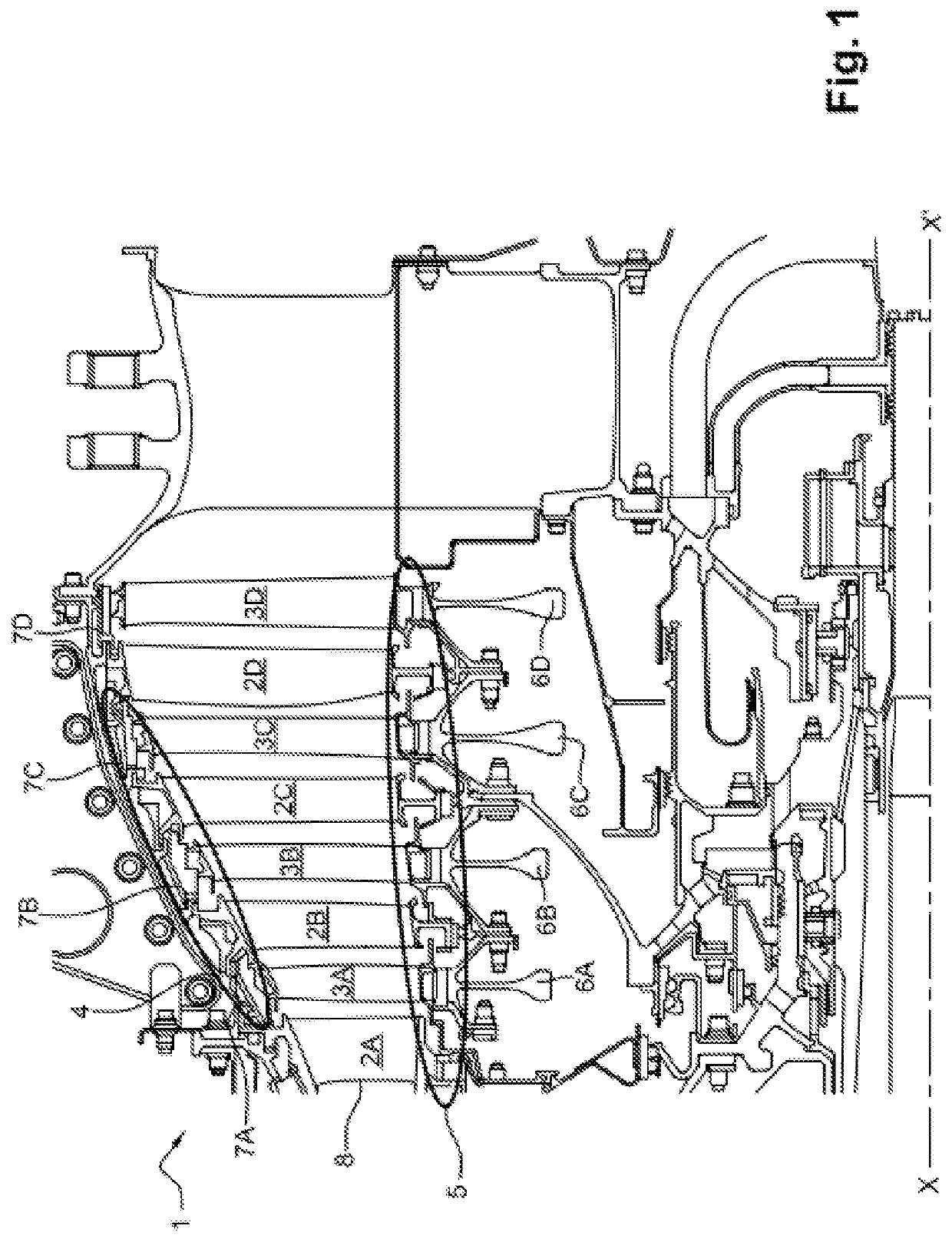
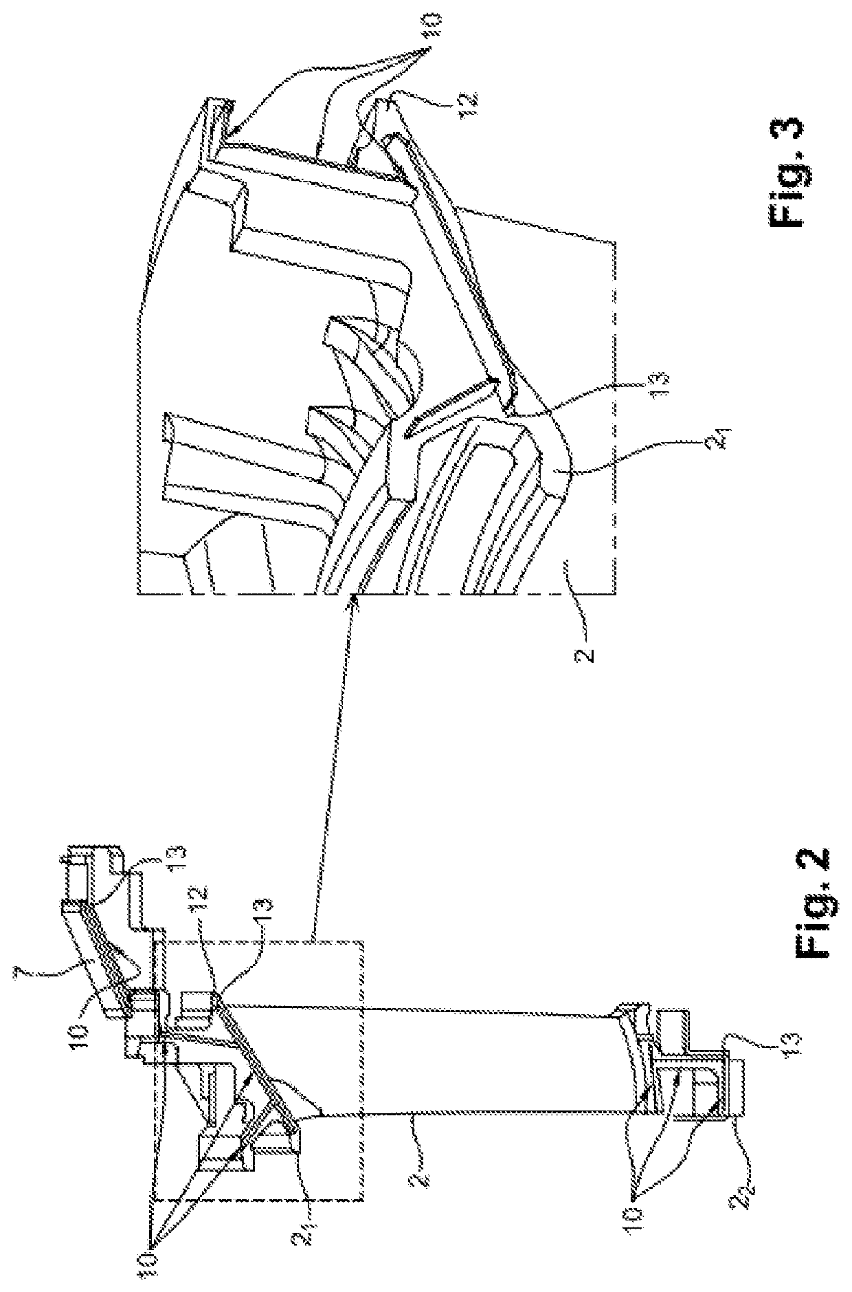
[0047]The invention relates to an assembly 100 enabling a seal to be maintained in a gas turbine 1 of a turboreactor or turboprop engine. In particular, assembly 100 according to the invention limits gas leaks outside airstream 8 of gas turbine 1 which can be seen in FIG. 1.

[0048]It should be noted that gas turbine 1, of longitudinal axis XX′, contains one or more stages enabling the gases being expelled from the combustion chamber to be expanded, where each stage contains a stator or distributor 2A, 2B, 2C and 2D followed by a rotor 3A, 3B, 3C and 3D. Each distributor 2A, 2B, 2C and 2D contains an annular row of stator blades 2 installed circumferentially around longitudinal axis XX′ of turbine 1 between an outside casing 4 and an internal structure 5, and each rotor 3A, 3B, 3C and 3D contains an annular row of rotary blades around said longitudinal axis XX′. The term “external casi...


PUM


Abstract

An assembly for gas turbine, includes a first part and a second part installed circumferentially around a longitudinal axis of the turbine, where the first part has a first side face adjacent to a second side face of the second part, and where a first aperture made in first side face is facing a second aperture made in second side face, a sealing plate fitted inside the first aperture and the second aperture, at least one longitudinal face of the sealing plate includes at least two projections made either side of a longitudinal central area of the sealing plate, wherein each projection is of a height chosen so as to reduce a clearance between the sealing plate and the first and second apertures.

Description

CROSS-REFERENCE TO RELATED APPLICATION[0001]This application claims priority to French Patent Application No. 1753844, filed May 2, 2017, the entire content of which is incorporated herein by reference in its entirety.TECHNICAL FIELD OF THE INVENTION[0002]The invention relates to the general field of turbomachines, and in particular to an assembly enabling a seal to be maintained in a gas turbine of a turboreactor or turboprop engine.TECHNOLOGICAL BACKGROUND OF THE INVENTION[0003]Gas turbines recover a proportion of the kinetic energy of the gases being expelled from the combustion chamber to operate the fan, compressor and accessories in a turboreactor, or alternatively to drive the transmission shaft of the propeller, the compressor and various accessories in a turboprop engine.[0004]FIG. 1 represents a longitudinal section of a gas turbine 1.[0005]Gas turbine 1 shown in FIG. 1, with longitudinal axis XX′, has four stages: each stage contains a distributor 2A, 2B, 2C and 2D, follo...

Claims


Application Information

Patent Timeline
Patent Type & Authority Patents(United States)
IPC IPC(8): F01D11/00F01D25/24F01D9/04F02C7/28F16J15/44
CPCF01D11/005F01D25/246F05D2220/32F01D9/041F05D2240/80F02C7/28F05D2240/57F16J15/44F05D2240/55Y02T50/60
Inventor ROUSSEAUX, HUGO LOUISBERCHE, EMMANUEL WILFRID LÉONBOSSAERT, ALEXANDRE XAVIER
Owner SN DETUDE & DE CONSTR DE MOTEURS DAVIATION S N E C M A
Why Eureka
Try Eureka