
Tibial prosthetic implant with offset stem

a tibial prosthetic and offset technology, applied in the field of total knee arthroplasty implants, can solve the problems of substantially offset central stems, inhibiting adequate initial stability and fixation, etc., and achieve the effect of optimal keel

Inactive Publication Date: 2001-07-10
WRIGHT MEDICAL TECH
View PDF5 Cites 73 Cited by
  • Summary
  • Abstract
  • Description
  • Claims
  • Application Information

AI Technical Summary

Benefits of technology

In order to accomplish this object, a tibial implant .[.according to the invention.]. .Iadd.for use in a normally shaped tibia .Iaddend.includes a stem that is offset from the center of the implant base. .Iadd.The offset is within a particular range for use in a normally shaped tibia. .Iaddend.Similarly to prior tibial implants, the present implant includes a base, an articulating portion, and attachment means for securing the implant to a patient's tibia during the implantation procedure. However, the tibial implant according to the invention also includes a stem extending from a point on the inferior surface of the base that is offset from a center point of the base. This offset enables the stem to extend into the central tibial canal when the implant is attached to the .Iadd.normally shaped .Iaddend.tibia with the inferior surface of the base abutting and aligning with the resected surface. The offset stem does not extend into or otherwise interfere with the cortical bone of the tibia. Also, optimal keel effect is achieved when the stem is central to the condylar weight bearing surface, providing equally dense bone on either side of the stem.

Problems solved by technology

Although the central location of the stem allowed a particular implant to be used for either the right or left knee, this stem position resulted in serious drawbacks.
The primary drawback was that the centrally located stem was substantially offset from the center of the tibial canal itself when the base of the implant was aligned with the resected tibial surface.
This interference with the cortical bone sometimes prevented the base of the implant from seating flush against the resected surface of the tibia, thereby inhibiting adequate initial stability and fixation which is essential for successful knee arthroplasty.

Method used


Image

  • Tibial prosthetic implant with offset stem
  • Tibial prosthetic implant with offset stem
  • Tibial prosthetic implant with offset stem

Examples


Embodiment Construction

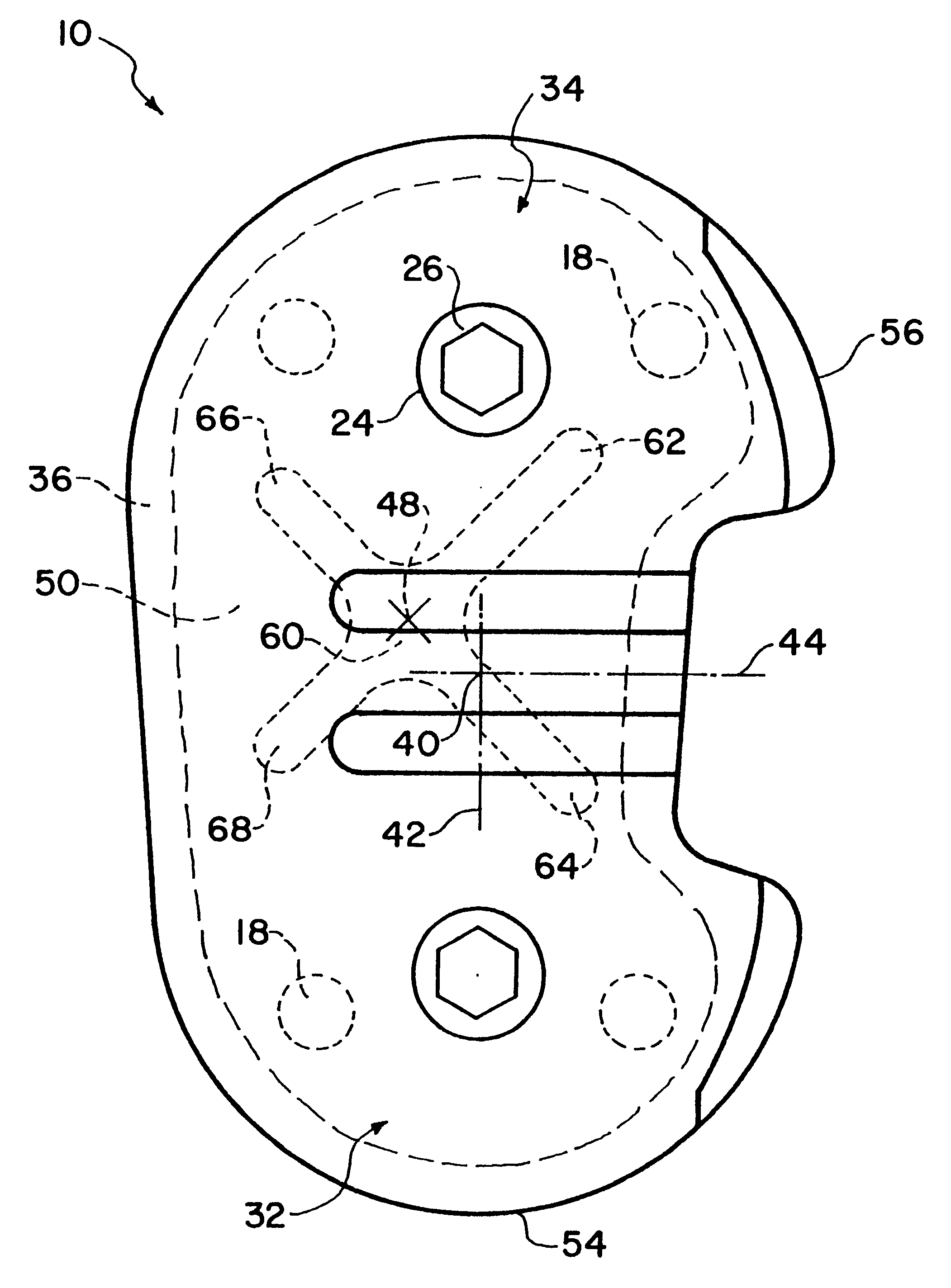
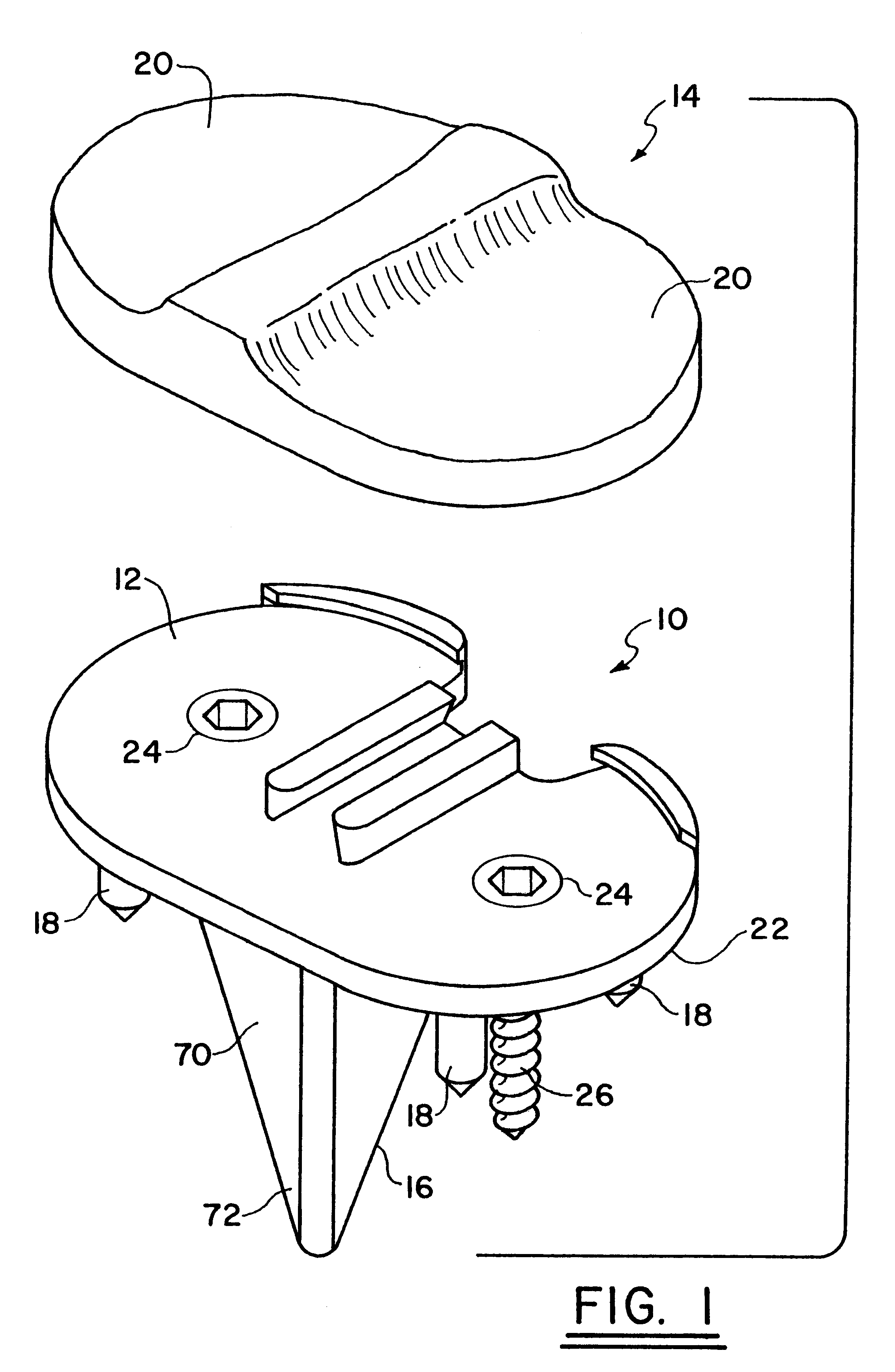
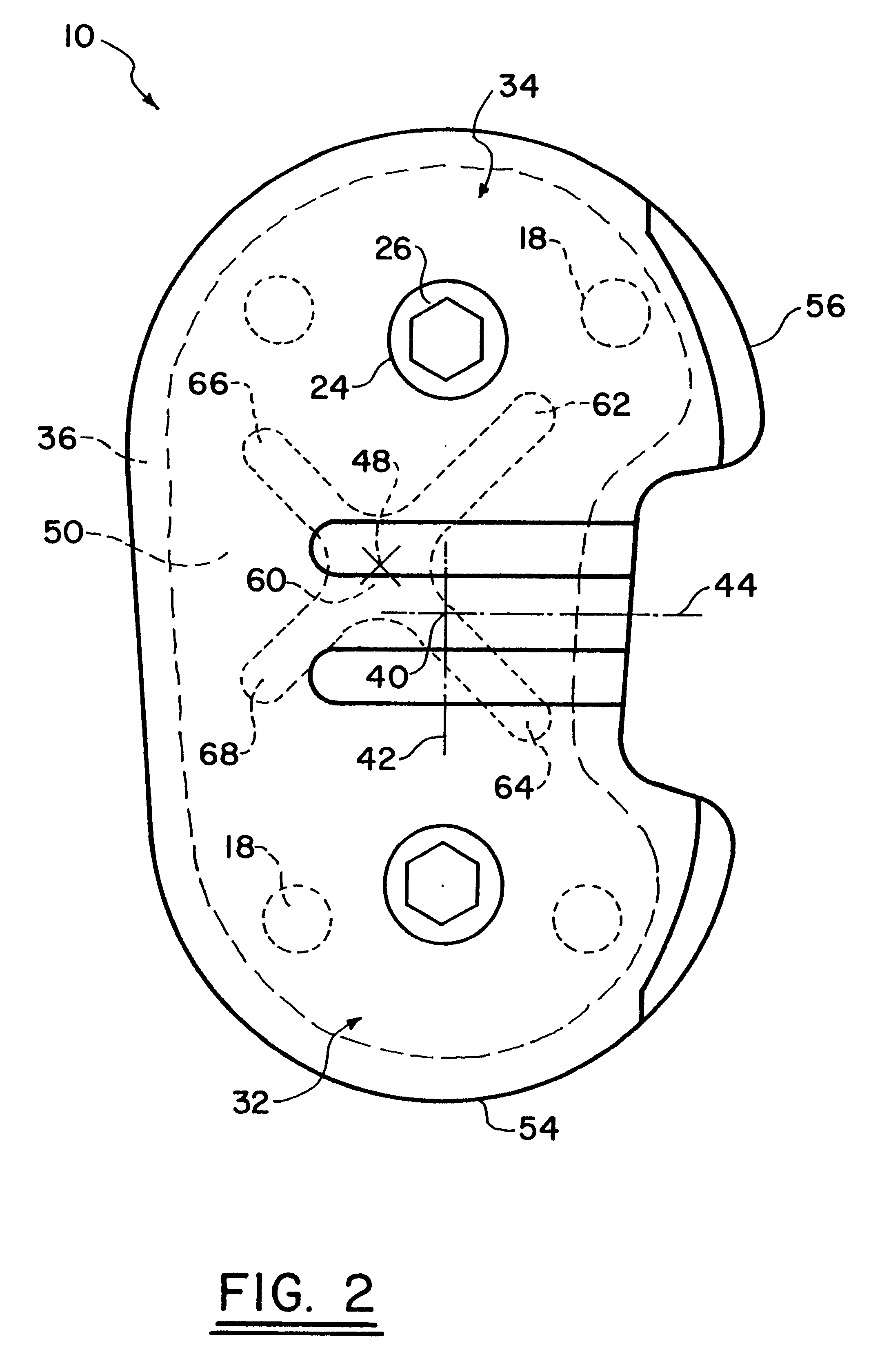
Referring particularly to FIG. 1 a tibial implant 10 embodying the principles of the invention includes a base 12 and an articulating portion 14. A stem 16, and preferably, a plurality of pegs 18 are connected to the base 12 of the implant. As shown in FIGS. 2 and 3, the base 12 also includes two openings 24 for receiving bone screws 26. The bone screws 26 along with the openings 24 form attachment means for attaching the implant 10 to the patient's tibia as described below.

Although the base 12 and articulating portion 14 may be integrally formed, the preferred form of the invention shown in the figures is modular with a base plate forming the base 12 and a separate insert comprising the articulating portion 14. The base plate and insert are adapted to connect together by suitable means to form the implant 10. The articulating portion or insert 14 is preferably formed from a suitable plastic material and includes articulating surfaces 20 adapted to articulate with the femoral condyl...


PUM


Abstract

A tibial prosthetic implant includes a base or base plate with an offset tibial stem. The base includes an inferior surface adapted to abut a resected surface of a patient's tibia and forms a base for articulating surfaces adapted to articulate with the patient's femoral condyles. The longitudinal center axis of the tibial stem extends from the inferior surface of the base and is offset from a center of the base. The offset places the stem in position to extend into the central canal of the tibia so that it does not substantially interfere with the cortical bone when the inferior surface of the base substantially abuts and aligns with the resected surface of the tibia.

Description

BACKGROUND OF THE INVENTIONThis invention relates to implants for total knee arthroplasty, and more particularly, to an improved stemmed tibial prosthetic implant.Total knee arthroplasty involves providing new articulating surfaces for the tibia, femur, and patella. The most common technique for providing new articulating surfaces for the tibia involves resecting an upper portion of the tibia and then attaching a prosthetic implant to the tibia over the resected surface. The tibial implant includes a base adapted to abut the resected surface of the tibia and an articulating portion which includes the new articulating surfaces. The base of the implant has a shape that is adapted to generally approximate the shape of the resected surface of the tibia so that the implant generally aligns with .Iadd.and completely covers .Iaddend.the resected surface when the base is properly attached to the tibia.The implant may also include a plurality of pegs extending from the lower or inferior surf...

Claims


Application Information

Patent Timeline
Patent Type & Authority Patents(United States)
IPC IPC(8): A61F2/38
CPCA61F2/389
Inventor BALDWIN, JAMES L.WHITLOCK, STEVEN I.
Owner WRIGHT MEDICAL TECH
Learn More