Panel cutting apparatus

a cutting machine and panel technology, applied in the field of rotary cutting devices, can solve the problems of improper alignment between the cutting die and the envelope blank, improper sealing, and prior art panel cutting machines, and achieve the effects of minimizing the number of magnetic strips, maximizing the number of vacuum orifices, and improving the distribution of magnets and air orifices

Inactive Publication Date: 2003-03-18
BEST CUTTING DIE
View PDF63 Cites 17 Cited by
  • Summary
  • Abstract
  • Description
  • Claims
  • Application Information

AI Technical Summary

Benefits of technology

It is a more specific object of the invention to provide an improved air delivery system which efficiently delivers vacuum to the die holder with minimal leakage.
In accordance with certain objects of the invention, the die holder may have an outer surface having a slot extending along the longitudinal axis for detachably receiving the leading end of the cutting die and a plurality of magnetic members disposed in the die holder surface for attracting the cutting die. In a preferred embodiment, the die holder may have a plurality of orifices disposed between adjacent magnetic members for delivering vacuum or air to the die holder surface. In order to maximize the number of orifices while minimizing the number of magnetic members, it is preferred that the magnetic members be disposed in a plurality of rows wherein each row contains alternating magnets and orifices and a row of orifices are disposed between each adjacent row of magnets.

Problems solved by technology

Unfortunately, the prior art panel cutting apparatuses suffer from numerous drawbacks.
Since the die holder typically rotates from zero to about 1500 rpm, it is extremely difficult to obtain a proper seal between the rotating vacuum tubes and the feed tubes which permits the envelope blank to move, resulting in improper alignment between the cutting die and the envelope blank.
Similarly, it is extremely difficult to obtain a proper seal at the vacuum orifices between the die holder and the drive shaft due to wear and abrasion, resulting in insufficient vacuum to carry the envelope blank and the panel and jamming of the cutting apparatus.
It is also difficult to apply the vacuum or air at the correct time during the rotation of the die holder.
The mechanical clamp assemblies, which clamp one or both of the leading and trailing ends of the cutting die, are relatively complicated devices which are time consuming to assemble and disassemble and expensive and difficult to manufacture.
Another drawback is the lack of adjustability of the apparatus to cut out panels of different sizes as well as different locations on the blank.
Attempts to provide an adjustable die holder capable of receiving different size cutting dies have been unsuccessful because the holding mechanisms, such as removable cover plates and holding keys, used to attach the cutting dies to the die holders leave significant areas without the vacuum orifices necessary to carry the envelope blank and the panel.
In addition, these attempts have resulted in die holders which become unbalanced during rotation.
Unfortunately, the forces resulting from the rotation of the die holder may cause the cutting die to slide laterally on the surface of the magnets.

Method used


Image

  • Panel cutting apparatus
  • Panel cutting apparatus
  • Panel cutting apparatus

Examples


Embodiment Construction

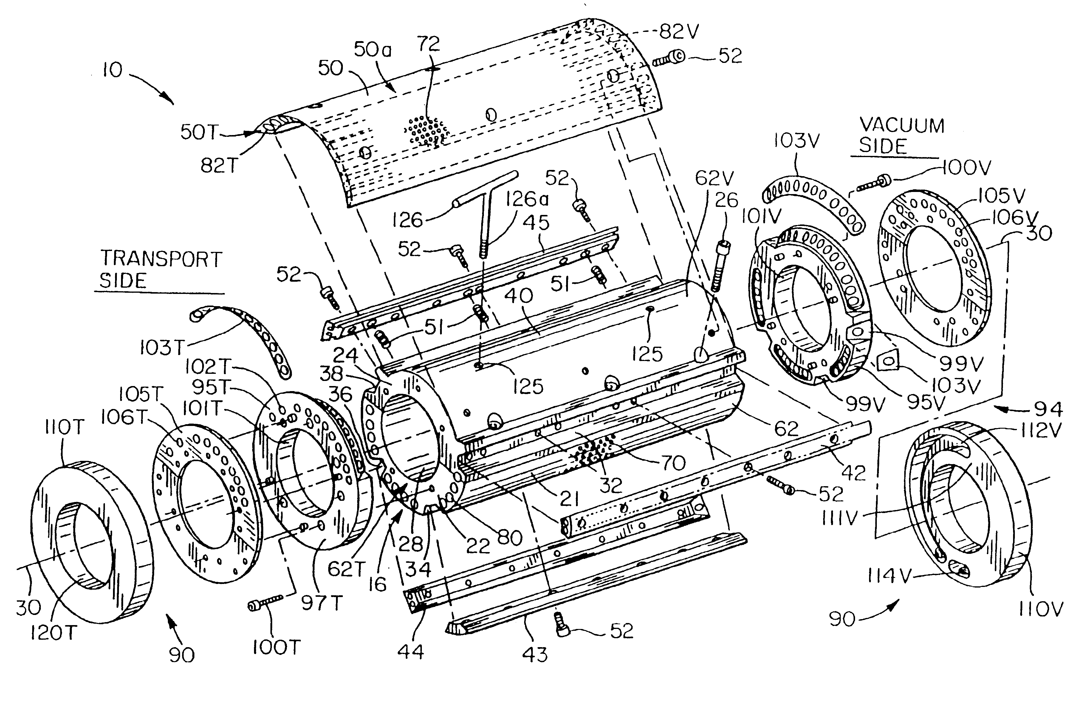
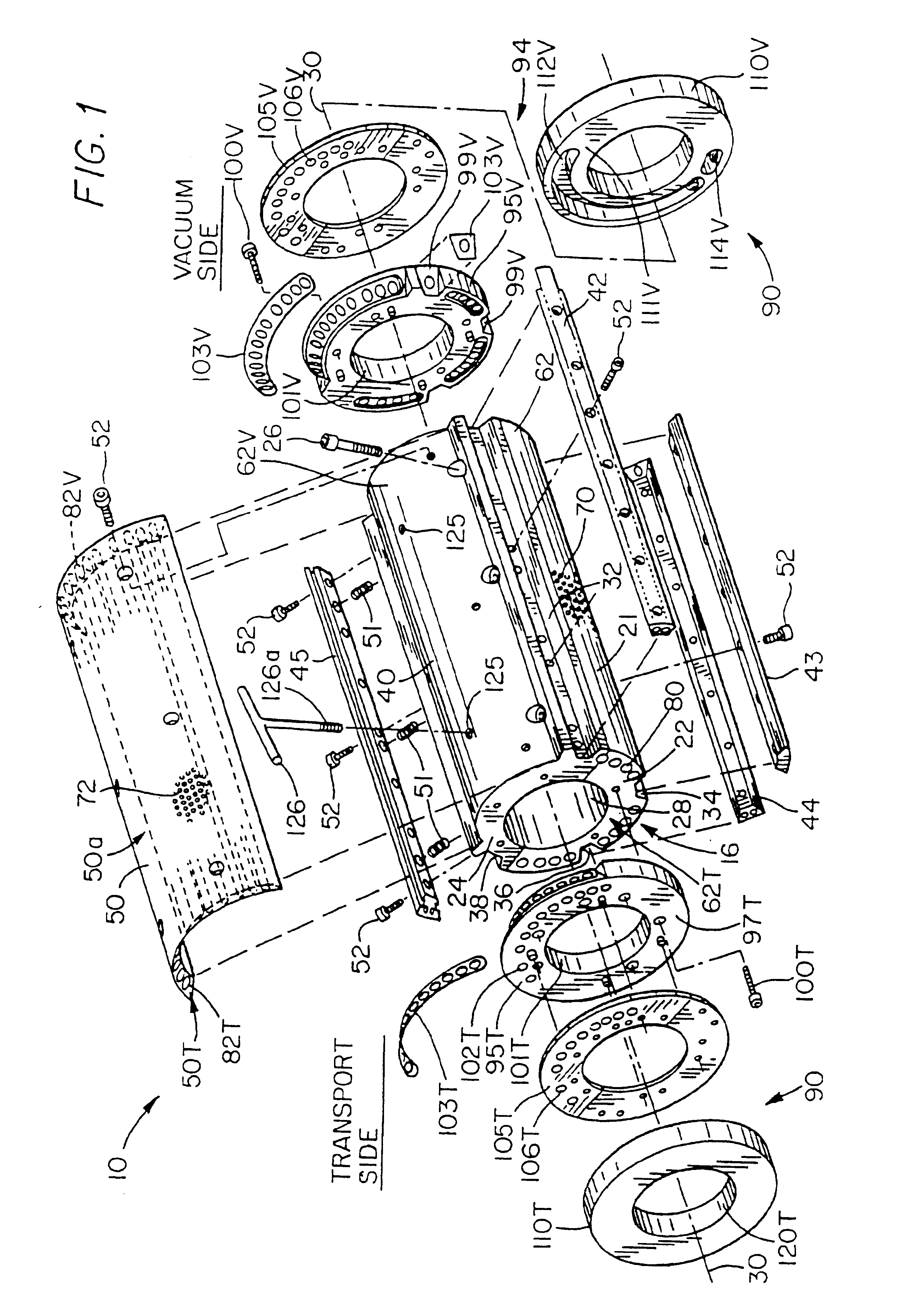
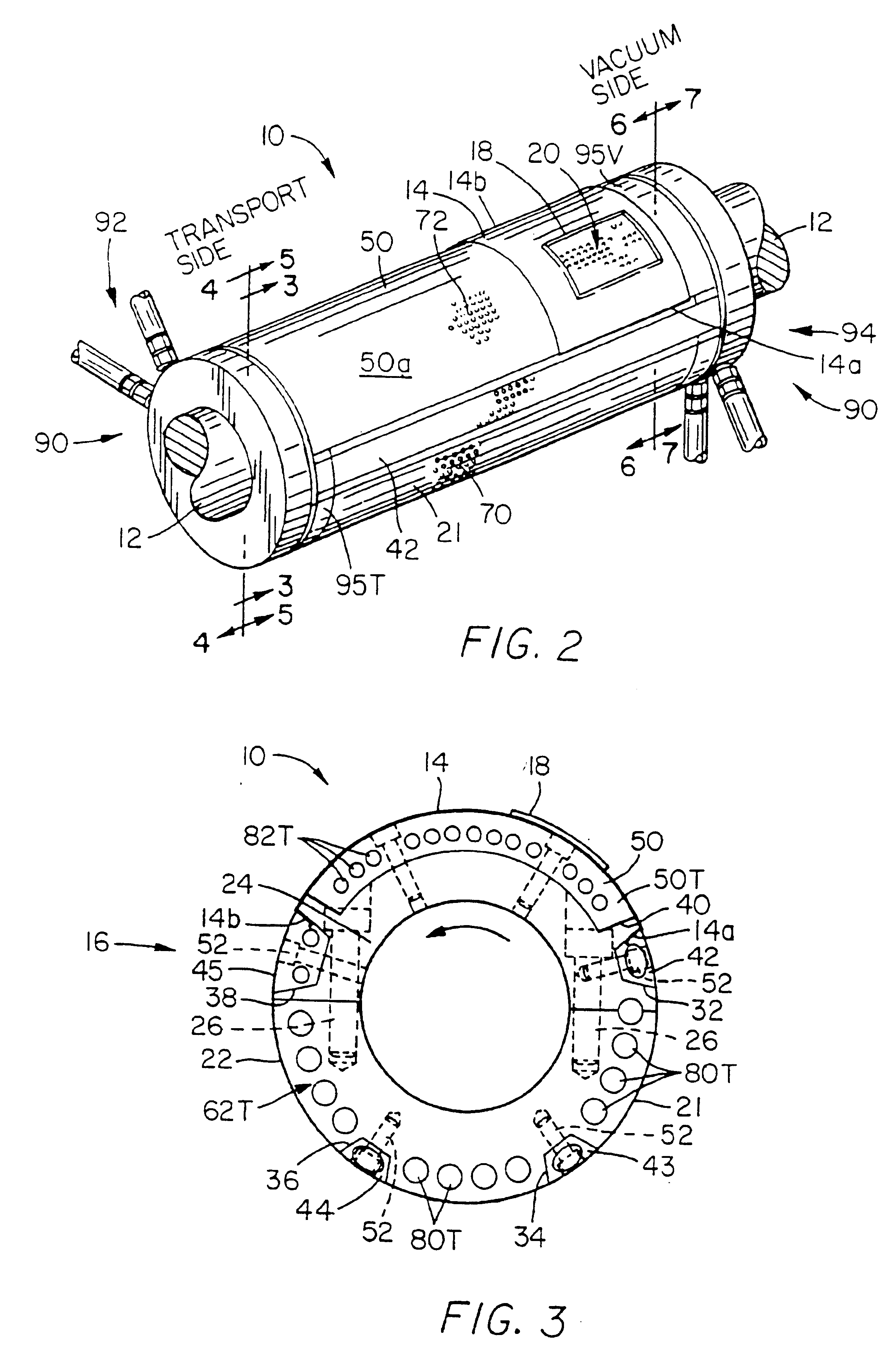
Referring to the drawings and more particularly to FIGS. 1-2, one embodiment of a rotary cutting tool 10 for cutting panels P and the like from sheet-like material such as envelopes and the like is mounted on a drive shaft 12 in accordance with the present invention. The cutting tool 10 comprises a cutting die 14 mounted on a die holder 16. The drive shaft 12 rotates the die holder 16 so that the cutting die 14 engages a different envelope blank B for each rotation of the die holder 16.

The die holder 16 cooperates with an air delivery assembly in order to receive and retain the envelope blank B during the cutting operation. One embodiment of an air delivery assembly in accordance with certain objects of the invention is generally referenced as 90 although conventional air delivery assemblies may also be used. The die holder 16 has a transport side which is generally depicted as the left side in FIGS. 1 and 2 and a vacuum side which is generally depicted as the right side. The transp...


PUM

PropertyMeasurementUnit
heightaaaaaaaaaa
lengthaaaaaaaaaa
lengthaaaaaaaaaa

Abstract

A rotary cutting assembly is provided for cutting a panel from an envelope blank or the like. The die holder has an outer surface and a plurality of surface orifices radially communicating with corresponding feed tubes for supplying vacuum or air to the surface and into the vicinity of the envelope blank. A novel air delivery assembly is provided for delivering vacuum and / or air to the die holder comprising a stationary plate disposed at least at one end of the die holder and defining a groove member for selectively supplying vacuum and / or air so that when rotation of die holder aligns the longitudinal feed tubes with the groove member a supply of vacuum or air is selectively supplied at the surface orifices of the die holder. Another embodiment of the die holder may have an outer surface having a extending along the longitudinal axis for detachably receiving the leading end of the cutting die and a plurality of magnetic members disposed in the die holder surface for attracting the cutting die. In order to maximize the number of orifices while minimizing the number of magnetic members, it is preferred that the magnetic members be disposed in a plurality of rows wherein each row contains alternating magnets and orifices and a row of orifices are disposed between each adjacent row of magnets. A novel valve assembly is provided for controlling the flow of air to the surface orifices.

Description

FIELD OF THE INVENTIONThe present invention relates generally to a rotary cutting device and more particularly a device for the cutting of windows, notches, orifices or other patterns in relatively thin, flexible sheet-like material in either sheet or web form.BACKGROUND OF THE INVENTIONMany envelopes have a transparent panel or window for allowing visual inspection of the enclosure. These window envelopes are manufactured from a web of paper material which is initially cut into blanks having a predetermined shape. A panel is subsequently cut from the blank by a panel cutting apparatus to form the window. Thereafter, the blank is then folded, gummed, printed and packaged to form the finished envelope.U.S. Pat. No. 4,823,659 to Falasconi describes a conventional rotary panel cutting apparatus comprising a cutting tool in the form of a cutting plate or die and a rotary die holder which brings the cutting die into successive contact with the envelope blanks which advance on a conveyor ...

Claims


Application Information

Patent Timeline
Patent Type & Authority Patents(United States)
IPC IPC(8): B31B19/20B31B19/00B26D7/26B26D7/01B26F1/38B26D7/18
CPCB26D7/018B26D7/1854B26D7/1863B26D7/2614B26D2007/2607B26F1/384B31B2160/10B31B70/20B31B2150/00B31B70/83Y10T83/9459Y10T83/9466Y10T83/0453Y10T83/4838Y10T83/2185
Inventor OKONSKI, FRANKPORENTO, SR., EDWARD J.
Owner BEST CUTTING DIE
Why Eureka
Try Eureka