Gasket attachment structure for refrigerant-seal

Inactive Publication Date: 2002-01-03
DENSO CORP
View PDF0 Cites 13 Cited by
  • Summary
  • Abstract
  • Description
  • Claims
  • Application Information

AI Technical Summary

Problems solved by technology

For example, when an O-ring made of a porous material is used as a seal member for connecting pipe members, refrigerant readily penetrates the porous material, and sealing performance may be decreased

Method used


Image

  • Gasket attachment structure for refrigerant-seal
  • Gasket attachment structure for refrigerant-seal
  • Gasket attachment structure for refrigerant-seal

Examples


first embodiment

[0030] A first preferred embodiment of the present invention will be now described with reference to FIGS. 1-5. In the first embodiment, for using carbon dioxide (CO.sub.2) as refrigerant, an approximately closed seal space is formed between both first and second connection members, and a semi-metal gasket is inserted into the seal space.

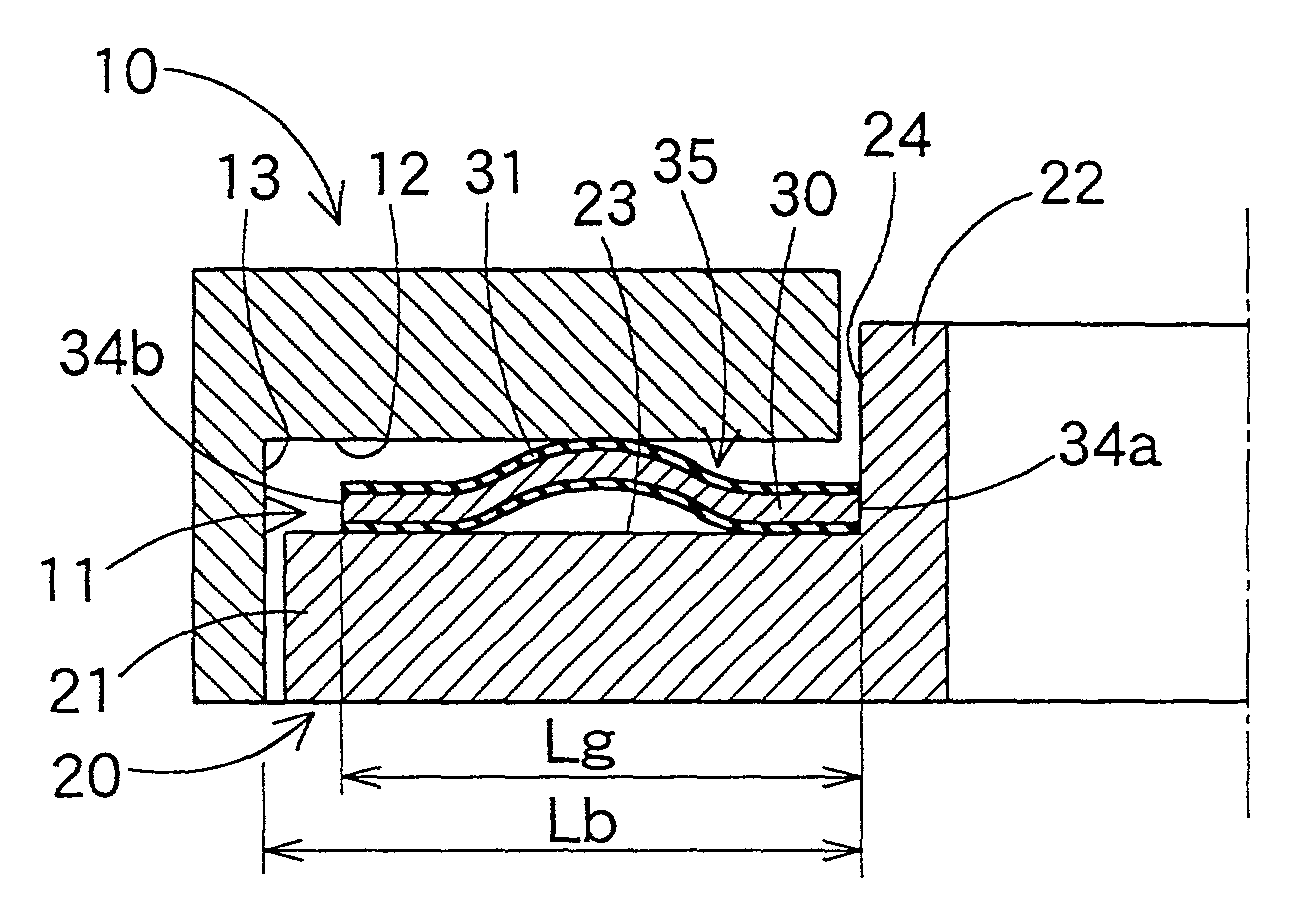
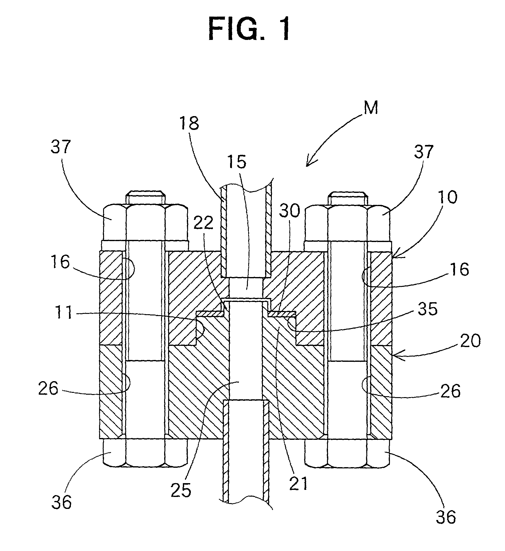
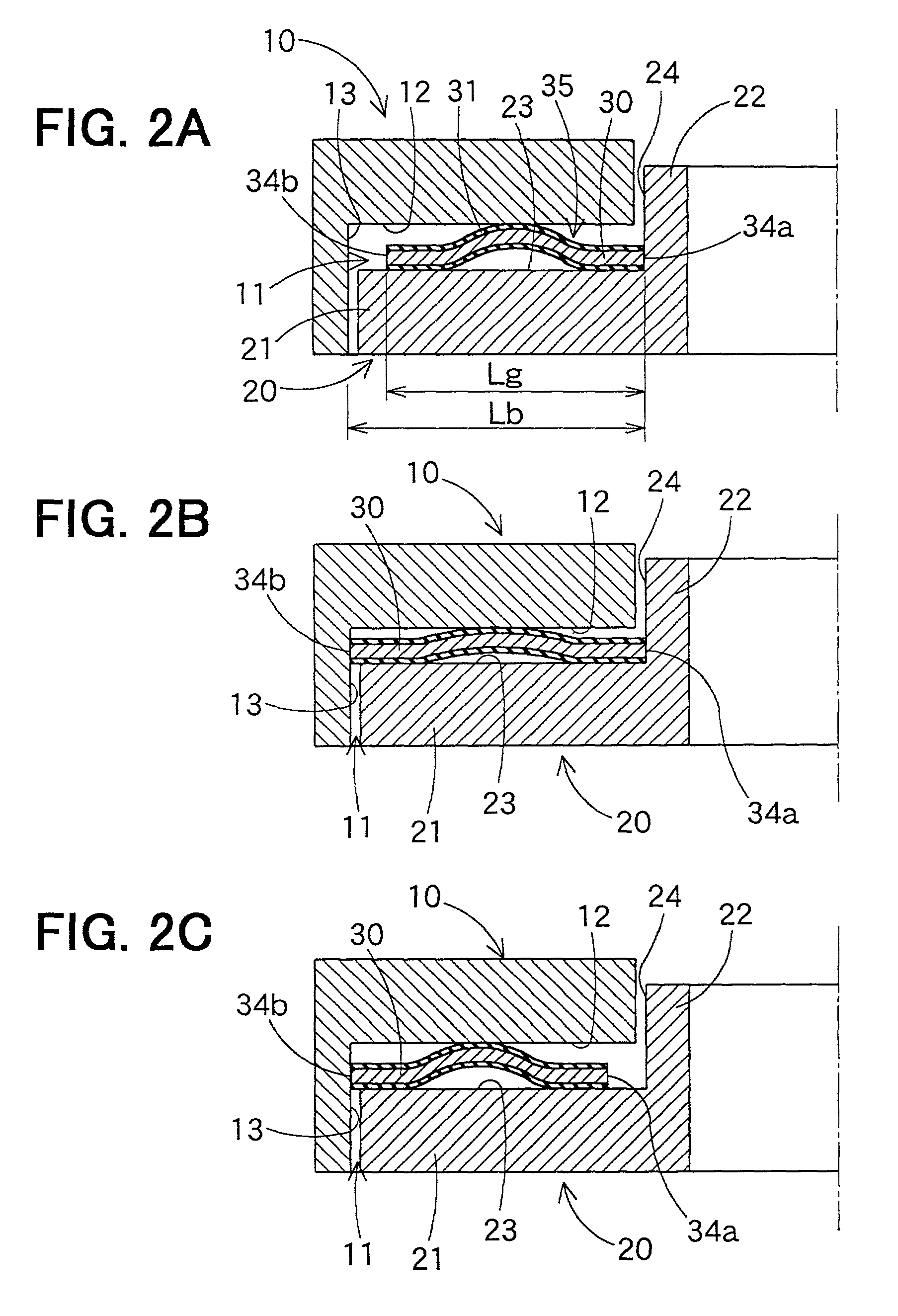
[0031] FIG. 1 shows an attachment structure M of a gasket for a refrigerant-seal. In FIG. 1, a first connection member 10 and a second connection member 20 are disposed to define a seal space 35, a flat gasket 30 is disposed in the seal space 35 to contact opposite surfaces of the first connection member 10 and the second connection member 20. The first connection member 10 is connected to a pipe member 18 at an upper side, and is disposed at an upper side of the second connection member 20.

[0032] A cylindrical recess portion 11 is provided in the first connection member 10 at a lower center portion to be recessed from a lower surface to an upper si...

fifth embodiment

[0048] A fifth preferred embodiment of the present invention will be now described with reference to FIGS. 10A and 10B. In the fifth embodiment, an attachment structure of a gasket 300 is formed into as shown in FIGS. 10A and 10B. The gasket 300 is formed substantially into a S-shape in cross-section to have both bead portions 310 at both sides. The gasket 300 has a metal portion 320, and both thin coating layers 330 provided at both inner and outer sides of the metal portion 320. In the attachment structure of FIGS. 10A, 10B, a first connection member 100 is formed into a circular shape having therein a hollow portion 110. On the other hand, a second connection member 200 is formed into a columnar to have a protrusion 210 inserted into the hollow portion 110 of the first connection member 100 and a flange surface (first wall surface) 220 around the protrusion 210. Each of the first and second connection members 100, 200 is formed around an axial line so that a refrigerant passage i...


PUM


Abstract

In an attachment structure of a gasket for a refrigerant-seal, both first and second connection members are disposed to define a seal space by first and second opposite surfaces and first and second wall surfaces, and the gasket having a beam portion is disposed in the seal space so that one end surface of the gasket is held on the first wall surface of the first connection member and the other end surface of the gasket is separated from the second wall surface of the second connection member by a predetermined clearance, before both the first and second connection members are fastened. After both the first and second connection members are fastened, the gasket extends, and the other end surface of the gasket press-contacts the second wall surface.

Description

[0001] This application is related to Japanese Patent Application No. 2000-191728 filed on Jun. 26, 2000, the contents of which are hereby incorporated by reference.[0002] 1. Field of the Invention[0003] The present invention relates to an attachment structure of a gasket used as a seal member of a refrigerant pipe having therein a refrigerant such as carbon dioxide (CO.sub.2), that is used at a high-pressure.[0004] 2. Description of Related Art:[0005] When carbon dioxide or the like is used as refrigerant of a refrigerant cycle so that a high-pressure side refrigerant pressure becomes equal to or larger than the critical pressure, the refrigerant pressure becomes higher by 10 times or more, as compared with a general refrigerant cycle using flon as refrigerant. With the increase of the refrigerant pressure in the high-pressure side pipe, a seal member attached to a connection part of pipe members is need to be constructed by a compressive structure. For example, when an O-ring made...

Claims


Application Information

Patent Timeline
IPC IPC(8): F16J15/08F16L19/02F16L23/18F25B41/00
CPCF16J15/0887F16L19/0218F16L23/18
Inventor IZUMI, RYOICHIINAGAKI, SHINICHI
Owner DENSO CORP
Why Eureka
Try Eureka