Scroll Fluid Machine

Active Publication Date: 2012-01-12
HITACHI IND EQUIP SYST CO LTD
View PDF6 Cites 14 Cited by
  • Summary
  • Abstract
  • Description
  • Claims
  • Application Information

AI Technical Summary

Benefits of technology

[0014]According to the embodiments of the present invention, a scroll fluid machine with a minimu

Problems solved by technology

JP-A No. 2004-340255 has a risk of leakage of the lubricant from the lip seal due to increased pressure in the orbiting bearing housing if the breathing hole is clogged with the lubricant.
This poses a risk of stepwise leakage of a lubricant from the seal lip if the internal pressure in the sealing device of the bearing

Method used


Image

  • Scroll Fluid Machine
  • Scroll Fluid Machine
  • Scroll Fluid Machine

Examples


first embodiment

[0029]A scroll compressor according to the first embodiment as an example of the scroll fluid machine according to the embodiments of the present invention will be described below with reference to FIG. 1 to FIG. 9.

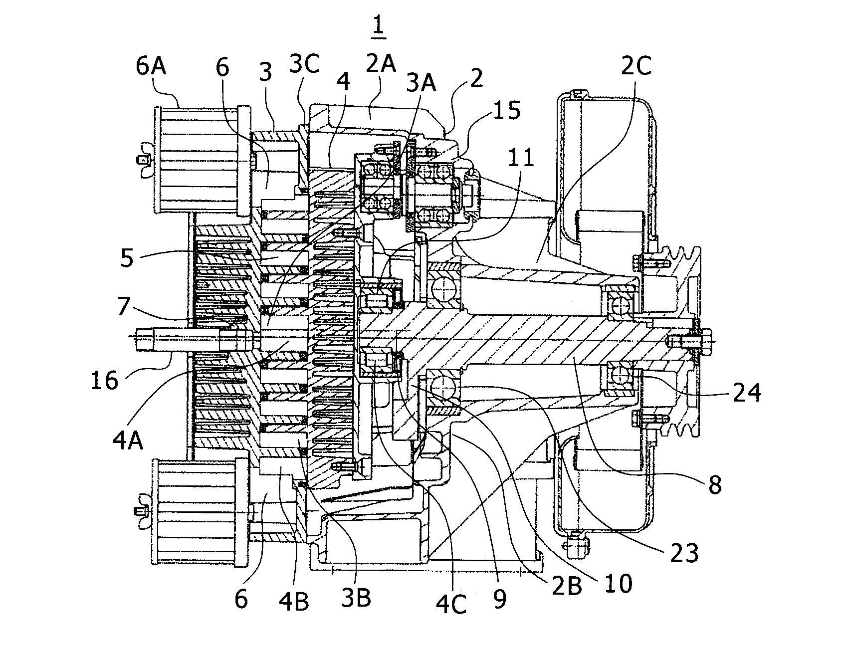
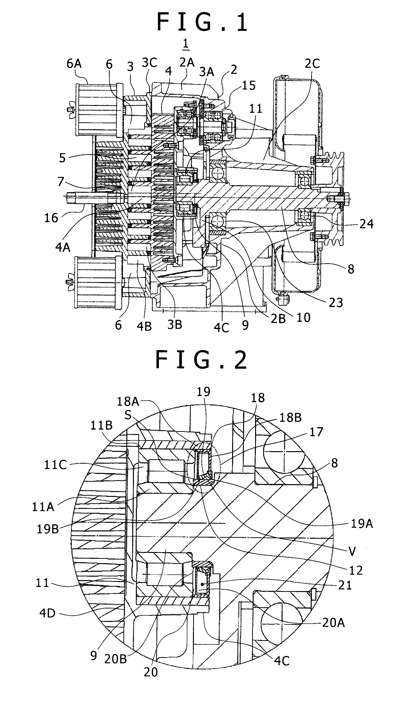
[0030]FIG. 1 is a cross-sectional view of a compressor according to the first embodiment. FIG. 2 is an enlarged view of part of the compressor around an orbiting bearing 11, which will be described later, in the first embodiment. FIGS. 1 and 2 show the compressor main-body 1 of a scroll air-compressor, which includes a casing 2 described below, a fixed scroll 3, an orbiting scroll 4, a drive shaft 8, a crank 9, an anti-rotation mechanism 15, and the like.

[0031]The casing 2 forms part of the outer shell of the compressor main-body 1, and is formed in a bottomed cylindrical shape having one closed end in the axis direction as shown in FIG. 1 and the other open end in the axis direction. Specifically, the casing 2 roughly include a cylinder 2A having the open end (closer to ...

second embodiment

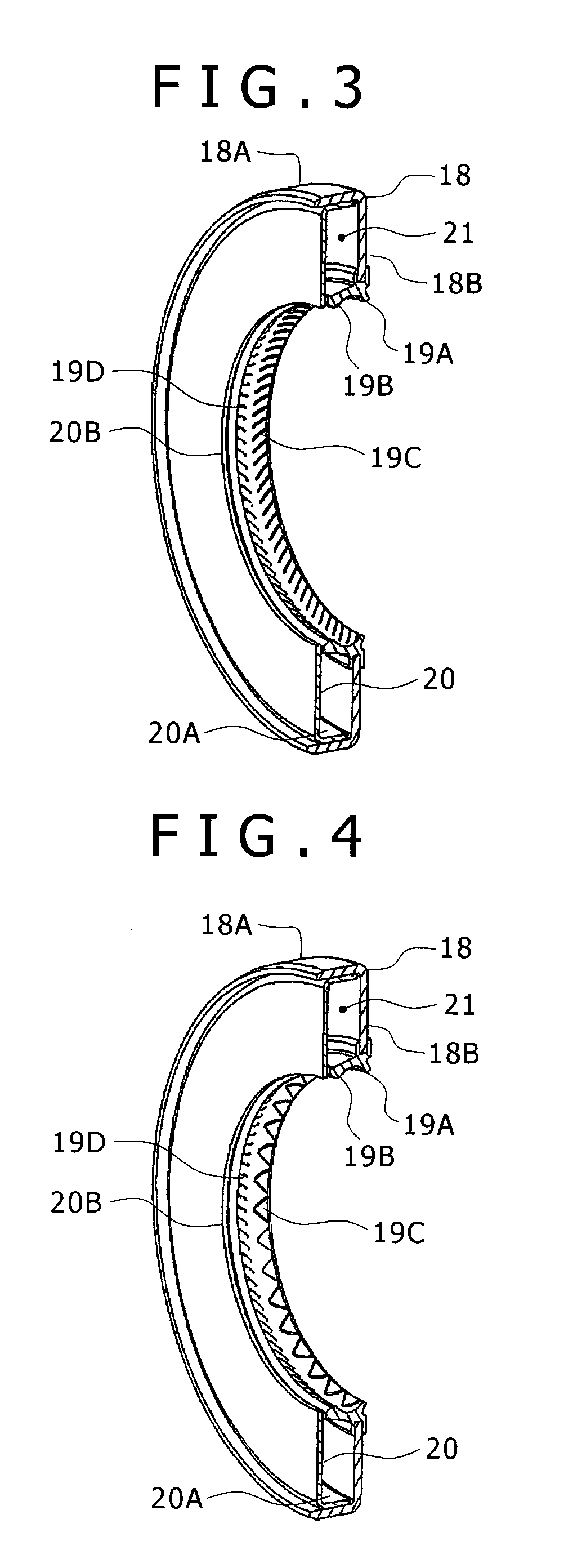
[0071]Next, the second embodiment according to the present invention will be described with reference to FIG. 10. The same or similar components in the second embodiment as or to those in the first embodiment are designated by the same reference signs and the description is omitted. The second embodiment illustrates the structure of the seal member 17 of a shape without the dust lip 19A as compared with the case of the first embodiment, when an area around the boss 4C is clean. The lip seal 19 molded integrally with the cored bar 18 of the seal member 17 includes only the oil lip 19B. The protrusions 19D are provided on the oil lip 19B. The sealed space 21 is connected to outside air through the oil-lip communication passage 22B. As a result, the interior of the sealed space 21 can be mainlined at atmospheric pressure at all times and also the sealing properties can be implemented because the pumping action is caused by the protrusions 19D.

third embodiment

[0072]Next, the third embodiment according to the present invention will be described with reference to FIG. 11. The same or similar components in the third embodiment as or to those in the first embodiment or the second embodiment are designated by the same reference signs and the description is omitted. The third embodiment illustrates a helical-shaped protrusion 19E provided on the oil lip 19B. A helical-shaped communication passage 22B is formed along and on each side of the protrusion 19E in order to maintain the interior of the sealed space 21 at atmospheric pressure. A plurality of seal lines are formed in the axis direction by the helical-shaped protrusion 19E, and improved sealing properties can be achieved by the pumping action.


PUM


Abstract

A scroll fluid machine with ensured reliability of an oil seal and a bearing even in a compressor operation at high rpm and high load is provided, which includes: a fixed scroll; an orbiting scroll facing the fixed scroll and having a boss provided on a face opposite to the fixed scroll; a drive shaft having a leading end mounted to the boss; an orbiting bearing supporting the drive shaft in connection with the orbiting scroll; and a seal member placed between the boss and the drive shaft to seal against a lubricant supplied to the orbiting bearing. The seal member has an oil lip producing action of moving the lubricant toward the orbiting bearing by rotation of the drive shaft. A communication passage is provided in the oil lip for communication between a space between the orbiting bearing and the seal member and a space outside the boss.

Description

[0001]This application claims the priority of Japanese Patent Application Nos. JP 2010-154416, filed Jul. 7, 2010, and JP 2011-129772, filed Jun. 10, 2011, the disclosures of which are expressly incorporated by reference herein in their entirety.BACKGROUND OF THE INVENTION[0002](i) Field of the Invention[0003]The present invention relates to a scroll fluid machine and, more particularly, to a scroll fluid machine for lubricating an orbiting bearing with grease.[0004](ii) Description of the Related Art[0005]JP-A No. 2004-340255 discloses a structure of an orbiting-bearing oil seal of a scroll compressor that includes an L-shaped cross-section and annular sealing member provided in the oil seal and having a breathing hole formed therein for a flow of outside air into the inside of the orbiting bearing housing.[0006]JP-A No. H08-254213 discloses a water-pump bearing hermetic structure in which an oil seal having a plurality of seal lips (lip seals) is placed in a dividing area between ...

Claims


Application Information

Patent Timeline
IPC IPC(8): F04C27/00F04C18/02F04C29/00F16C33/72F16J15/3244F16J15/3252
CPCF04C27/009F04C18/0215
Inventor IWANO, KIMINORISAKAMOTO, SUSUMUKOBAYASHI, YOSHIOTASHIRO, KOICHI
Owner HITACHI IND EQUIP SYST CO LTD
Why Eureka
Try Eureka