Variable temperature seat climate control system

a seat and variable temperature technology, applied in the field of variable temperature seats, can solve the problems of less effective use of temperature conditioned air in the cabin of the vehicle to heat or cool the occupant, maximize power efficiency, and seat known in the art that provides temperature conditioned air to the occupant do not operate in an electrically efficient manner, so as to minimize the possible discomfort of the occupan

Inactive Publication Date: 2003-06-03
GENTHERM INC
View PDF23 Cites 310 Cited by
  • Summary
  • Abstract
  • Description
  • Claims
  • Application Information

AI Technical Summary

Benefits of technology

The control algorithm is also designed to limit the power to the Peltier modules during the cooling mode of operation when the temperature of the cooling air directed to the occupant exceeds a predetermined minimum cooling temperature and the temperature has not been adjusted for a predetermined period of time, thus minimizing possible occupant discomfort associ

Problems solved by technology

In such applications the use of distributing temperature conditioned air into the cabin of the vehicle to heat or cool the occupant is less effective due to the somewhat limited surface area of contact with the occupant's body.
The seat constructions known in the art, although addressing the need to provide a more efficient method of heating or cooling the occupant, has not addressed the need to provide temperature conditioned air to an occupant in a manner that both maximizes occupant comfort and maximizes power efficiency.
The seats known in the art that provide temperature conditioned air to an occupant do not operate in an electrically efficient manner.
The practice of dissipating excess power instead of providing only that amount of power necessary to operate the Peltier thermoelectric devices makes such seats unsuited for such power sensitive applications as the electric vehicle as well as other applications where electrical efficiency is a concern.
However, the seats known in the ar

Method used


Image

  • Variable temperature seat climate control system
  • Variable temperature seat climate control system
  • Variable temperature seat climate control system

Examples


first embodiment

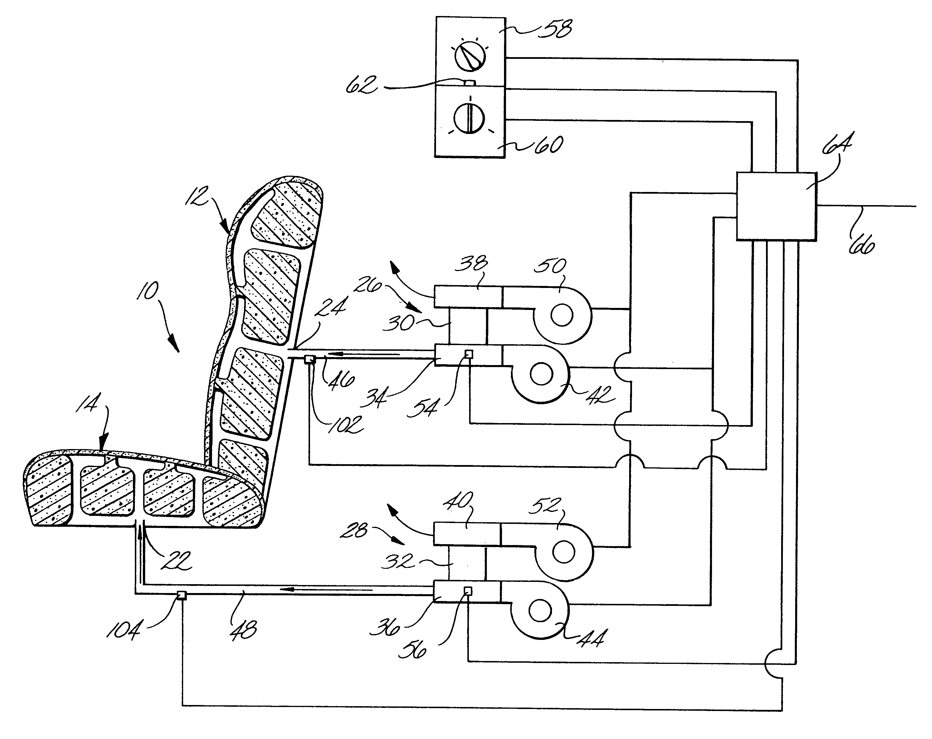
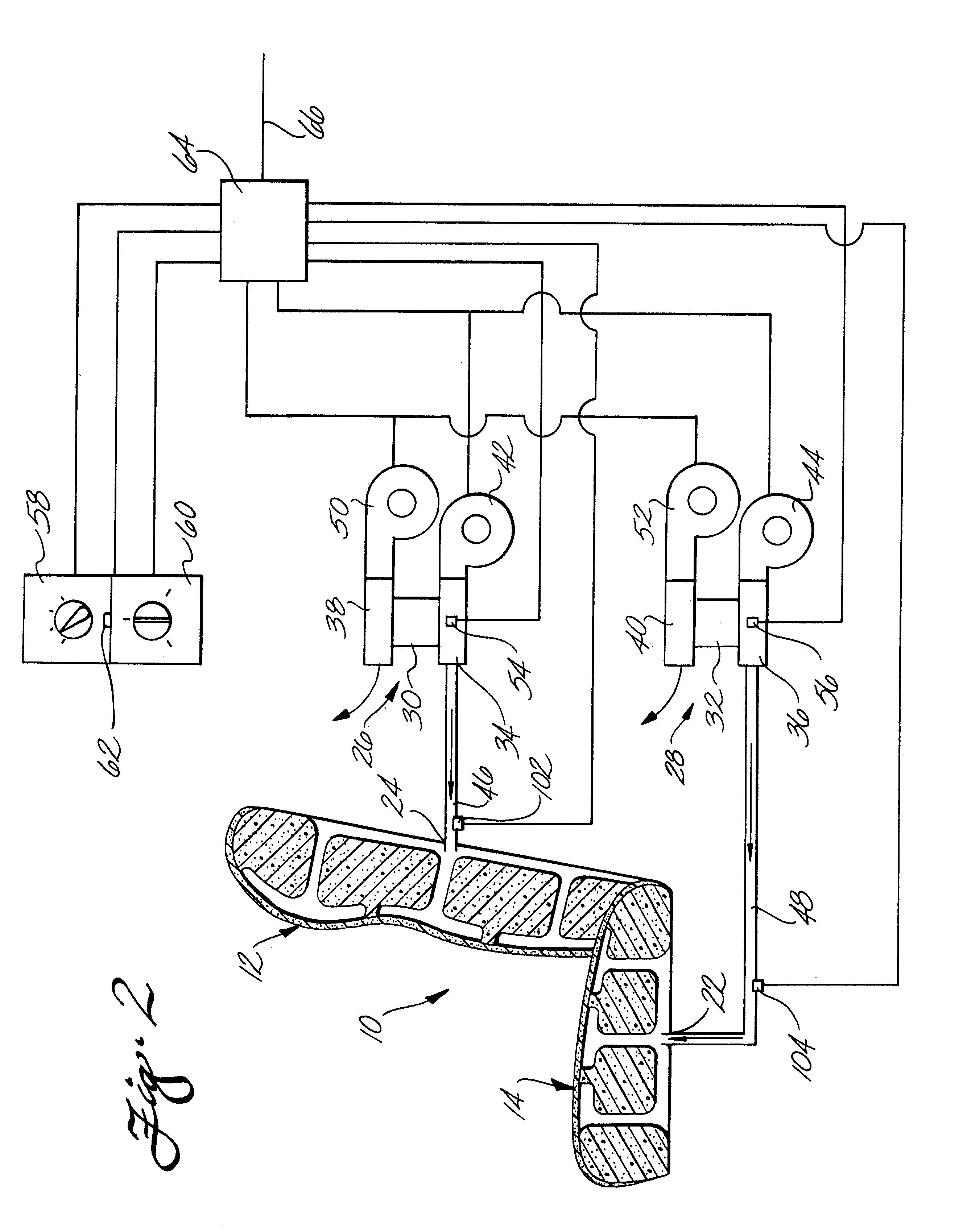
The first embodiment comprises conditioned air temperature sensors 102 and 104 positioned in the air flow of the temperature conditioned air passing to the seat, back and seat bottom, respectively, as shown in FIG. 2. The conditioned air temperature sensors are electrically connected to the controller 64. The temperature climate control algorithm described above and illustrated in FIG. 3 is configured to deactivate the Peltier modules in the event that the temperature of the conditioned air is greater than about 325.degree. K. or below about 297.degree. K. While the Peltier modules are deactivated the main exchanger fans continue to run.

FIG. 4 shows a second embodiment of the TCCS according to the practice of the present invention. The second embodiment is similar to the first embodiment in all respects, except for the addition of at least one ambient air temperature sensor 102 to monitor the temperature of the air outside of the VTS surrounding the occupant. The temperature sensor ...

second embodiment

The second embodiment also comprises conditioned air temperature sensors 128 and 130 positioned in the air flow of the temperature conditioned air passing to the seat, back and bottom, respectively, as shown in FIG. 4. The conditioned air temperature sensors are electrically connected to the controller 64. The temperature climate control algorithm described above and illustrated in FIG. 5 is configured to deactivate the Peltier modules in the event that the temperature of the conditioned air directed to the occupant is greater than about 325.degree. K. or below about 297.degree. K. While the Peltier modules are deactivated the main exchanger fans continue to run.

FIG. 6 shows a third embodiment of the TCCS according to the practice of this invention. The third embodiment is similar to the first embodiment in all respects except for two. One is the addition of at least one ambient air temperature sensor 132 to monitor the temperature of the air outside of the VTS surrounding the occup...

third embodiment

the TCCS as specifically described above and illustrated in FIG. 6 is used for controlling multiple VTSs in multi-occupant applications such as buses, trains, planes and the like. In such an application the main exchanger fan, waste exchanger fan, Peltier modules, temperature sensor, and weight sensitive switch from each VTS are electrically connected to a common controller. Multiple ambient air temperature sensors may be placed at different locations within the vehicle to provide an accurate temperature profile throughout the interior of the vehicle. The common controller is configured to accommodate inputs from the multiple ambient air temperature sensors. The common controller may be configured to control the main fan speed and mode of operation for the Peltier modules in the same manner as that specifically described above and illustrated in FIG. 7, taking into account the possibility of different ambient temperature zones within the vehicle surrounding each VTS.

Although limited...


PUM


Abstract

A temperature climate control system comprises a variable temperature seat, at least one heat pump, at least one heat pump temperature sensor, and a controller. Each heat pump comprises a number of Peltier thermoelectric modules for temperature conditioning the air in a main heat exchanger and a main exchanger fan for passing the conditioned air from the main exchanger to the variable temperature seat. The Peltier modules and each main fan may be manually adjusted via a temperature switch and a fan switch, respectively. Additionally, the temperature climate control system may comprise a number of additional temperature sensors to monitor the temperature of the ambient air surrounding the occupant as well as the temperature of the conditioned air directed to the occupant. The controller is configured to automatically regulate the operation of the Peltier modules and/or each main fan according to a temperature climate control algorithm designed both to maximize occupant comfort during normal operation, and minimize possible equipment damage, occupant discomfort, or occupant injury in the event of a heat pump malfunction.

Description

FIELD OF THE INVENTIONThe present invention relates generally to a variable temperature seat and, more specifically, to a method and apparatus for controlling the flow and temperature of a heating or cooling medium through the seat to an occupant positioned in such seat.BACKGROUND OF THE INVENTIONCooling or heating occupants of buildings, homes, automobiles and the like is generally carried out by convection through modifying the temperature of air surrounding the occupants environment. The effectiveness of convection heating or cooling is largely dependent on the ability of the temperature conditioned air to contact and surround all portions of the occupants's body. Heating and cooling occupants through convention is generally thought to be efficient in such applications as homes, offices, and other like structures where the occupants are not stationary or fixed in one position but, rather are moving around allowing maximum contact with the temperature treated air.In other applicat...

Claims


Application Information

Patent Timeline
IPC IPC(8): A47C7/72A47C7/74B60H1/00B60N2/56F25B21/02F25B21/04B60H1/32
CPCA47C7/74B60H1/00285B60H1/00478B60H2001/003B60N2/5628B60N2/5642B60N2/5678F25B21/04B60N2/5657
Inventor GALLUP, DAVID F.NOLES, DAVID R.WILLIS, RICHARD R.
Owner GENTHERM INC
Why Eureka
Try Eureka