Mold-pressing device

Inactive Publication Date: 2003-08-19
WALTJUN INDAL
View PDF23 Cites 23 Cited by
  • Summary
  • Abstract
  • Description
  • Claims
  • Application Information

AI Technical Summary

Benefits of technology

It is still a further object of the present invention to provide the above mold-pressing device in which the mold block is replacea

Problems solved by technology

Such procedure is very troublesome and waste-consuming.
However, in the case that the paper has a consid

Method used


Image

  • Mold-pressing device
  • Mold-pressing device
  • Mold-pressing device

Examples


Embodiment Construction

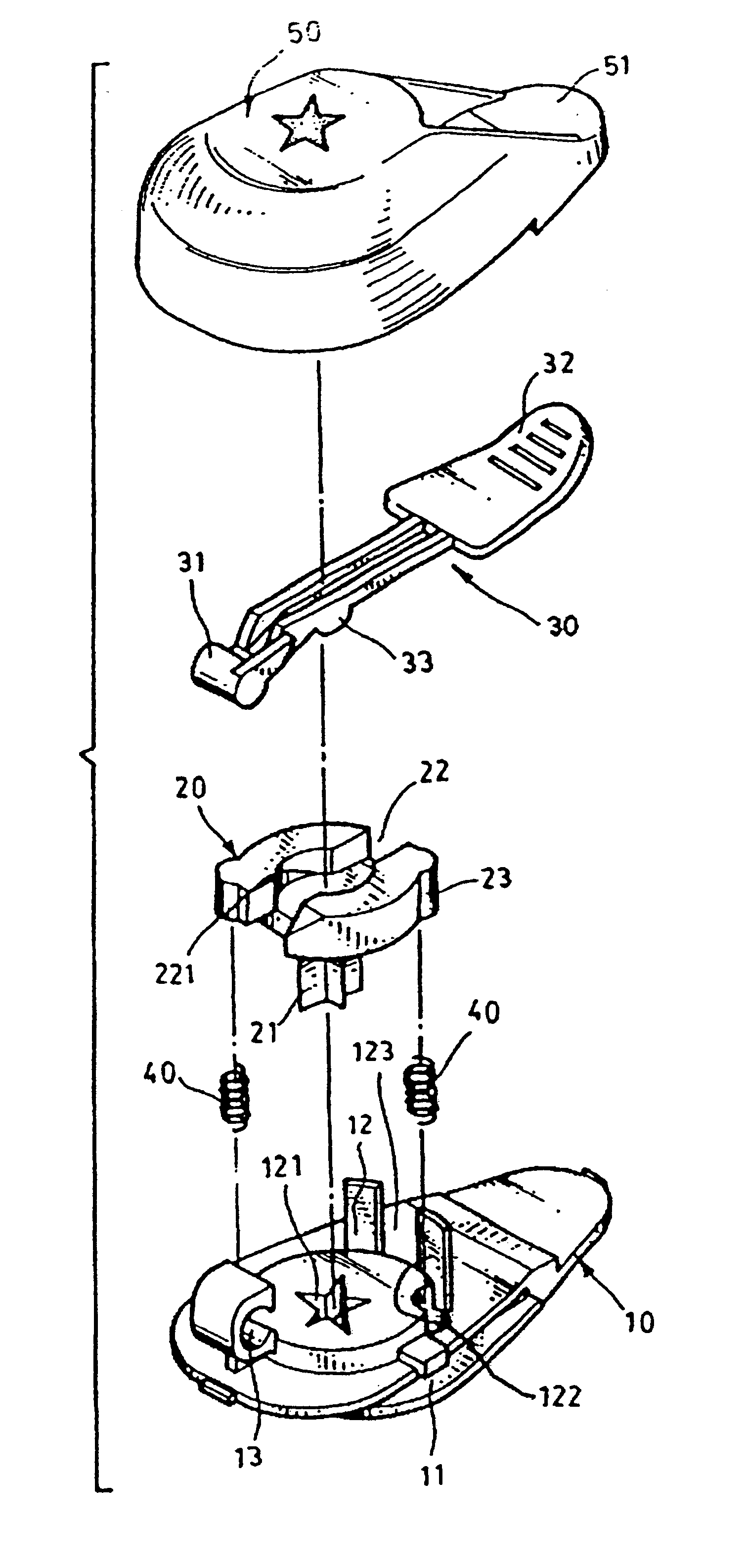
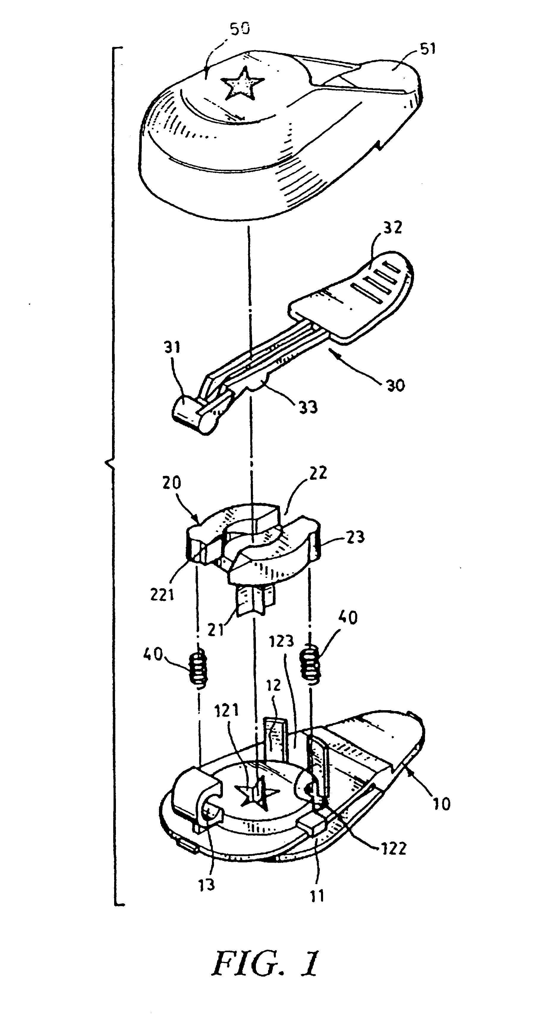
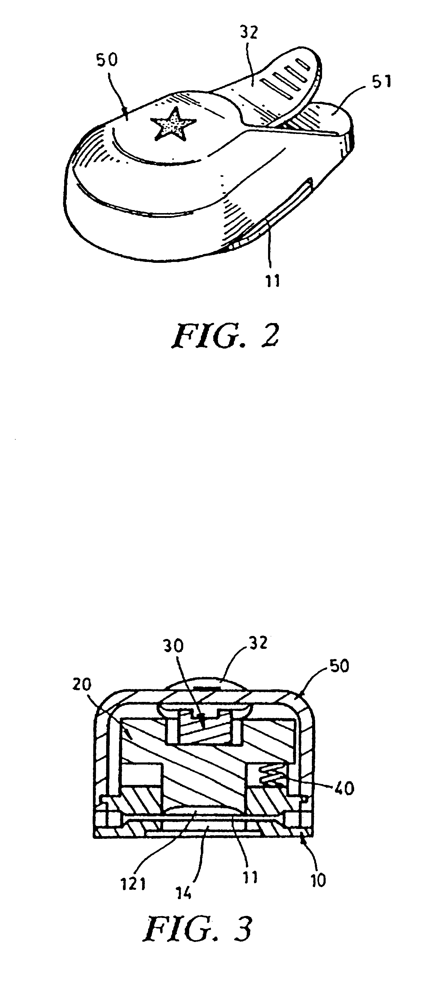
Please refer to FIGS. 1 to 5. The mold-pressing device of the present invention includes a seat body 10 formed with a horizontal fissure 11 at one end and a vertical chamber 12. The bottom of the chamber 12 is formed with an opening 121 communicated with the fissure 11. An upward extension 122 is disposed on rear side of the chamber 12. A pair of opposite notches 123 are formed on the periphery of the chamber 12. An insertion cavity 13 is disposed in one notch 123 opposite to the other notch 123. The bottom of the seat body 10 is formed with a through hole 14 communicated with the fissure 11 opposite to the opening 121.

A mold block 20 is disposed on the seat body 20. One face of the mold block 20 facing the fissure 11 is disposed with a solid die 21 such as an animal or a cartoon picture. The other face of the mold block 20 is disposed with a channel 22 passing through the mold block 20. Two opposite recesses 221 are formed on two sides of the channel 22. The mold block 20 is dispos...


PUM

PropertyMeasurementUnit
Shapeaaaaaaaaaa
Resilienceaaaaaaaaaa

Abstract

A mold-pressing device including a seat body formed with a horizontal fissure at one end and a vertical chamber communicated with the fissure. A mold block is disposed in the chamber. One face of the mold block is disposed with a solid die, while the other face of the mold block is disposed with a channel passing through the mold block. A pressing lever is pivotally disposed in the channel of the mold block. A housing covers the seat body and is formed with a window for a pressing section of the pressing lever to extend therethrough. In use, a paper or a sheet is pushed into the fissure of the seat body and then the pressing section of the pressing lever is depressed, whereby a protuberance of the pressing lever is moved downward to force the mold block downward with the die punching the paper or the sheet placed in the fissure. Therefore, a product with a shape as that of the die is formed.

Description

BACKGROUND OF THE INVENTIONThe present invention relates to a mold-pressing device in which a mold block is movably disposed in a seat body. A pressing lever is pivotally disposed on the seat body for pressing the mold block. The seat body is formed with a fissure and the mold block is formed with a die. A paper or a sheet can be pushed into the fissure of the seat body and then the pressing section of the pressing lever is depressed, whereby the mold block is forced downward with the die punching the paper or the sheet placed in the fissure. Therefore, many products with a shape as that of the die can be formed.Generally, when it is desired to manufacture a great amount of identical pictures, first many papers or sheets are stamped with a mold painted with ink. Then the pictures are cut off by a knife or a pair of scissors. Such procedure is very troublesome and waste-consuming. Alternatively, many papers can be stacked and cut off at one time to save time. However, in the case tha...

Claims


Application Information

Patent Timeline
IPC IPC(8): B26F1/32B26F1/36
CPCB26D3/10B26F1/36Y10T83/222Y10T83/8785Y10T83/885Y10T83/9428
Inventor LEE, CHENG HOCHEN, CHENG NAN
Owner WALTJUN INDAL
Why Eureka
Try Eureka