Torque transmitting and torsion damping apparatus for use in motor vehicles

Inactive Publication Date: 2003-09-30
LUK LAMELLEN & KUPPLUNGSBAU BETEILIGUNGS KG
View PDF12 Cites 9 Cited by
  • Summary
  • Abstract
  • Description
  • Claims
  • Application Information

AI Technical Summary

Benefits of technology

An object of the invention is to provide a torsion damping apparatus which can be used in motor vehicles as a superior substitute for heretofore known

Problems solved by technology

This can adversely influence the operation and useful life of the bearing, especially if the races of the bearing are directly connected to or in direct contact with the adjacent flywheels.
Nevertheless, such torsion damping apparatus failed to gain popularity in the automotive and other industries, primarily because the useful life of the bearing or bearings between the flywheels is relatively short.
The bearing or bearings are one of the critical elements in these torsion damping

Method used


Image

  • Torque transmitting and torsion damping apparatus for use in motor vehicles
  • Torque transmitting and torsion damping apparatus for use in motor vehicles
  • Torque transmitting and torsion damping apparatus for use in motor vehicles

Examples


Example

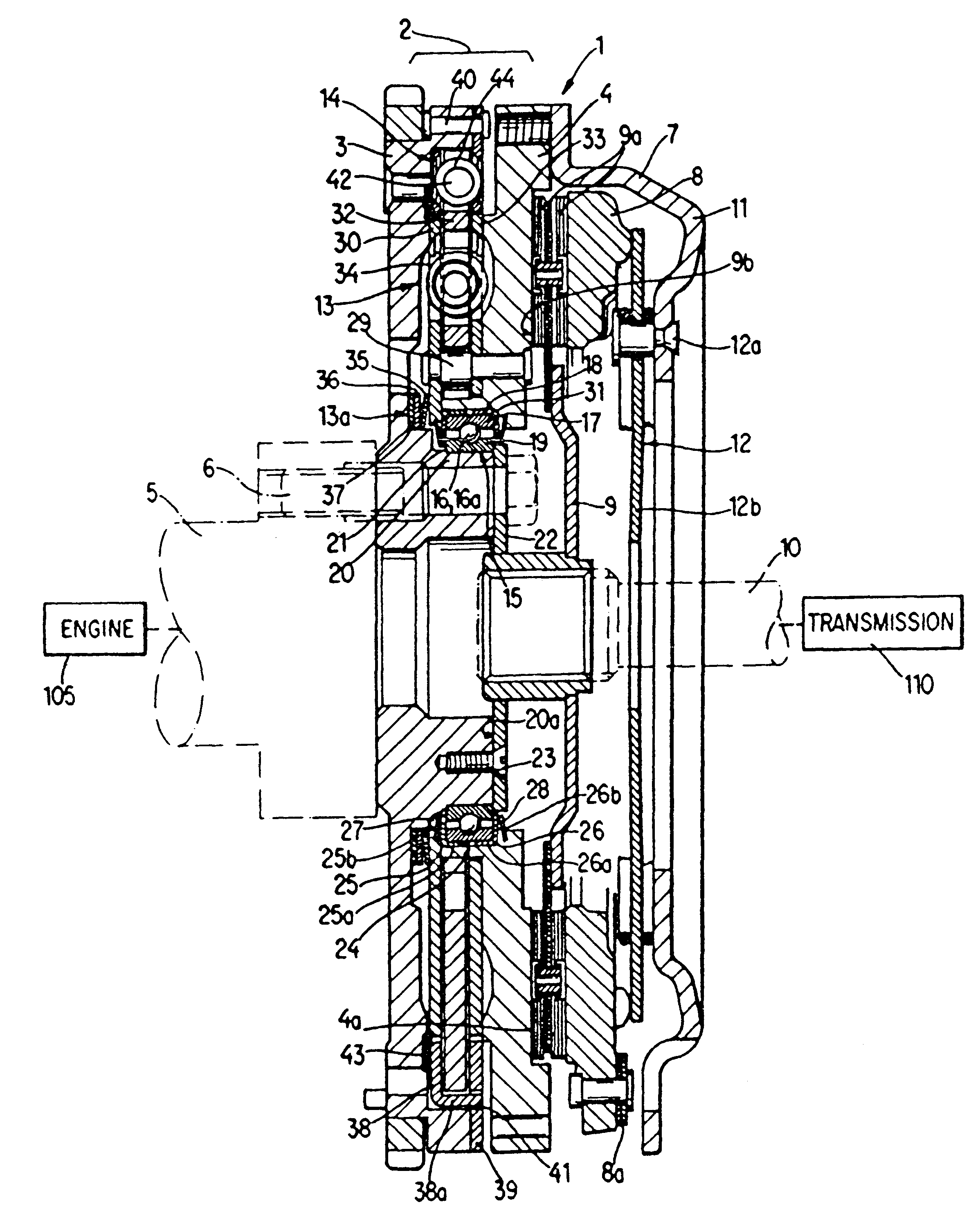
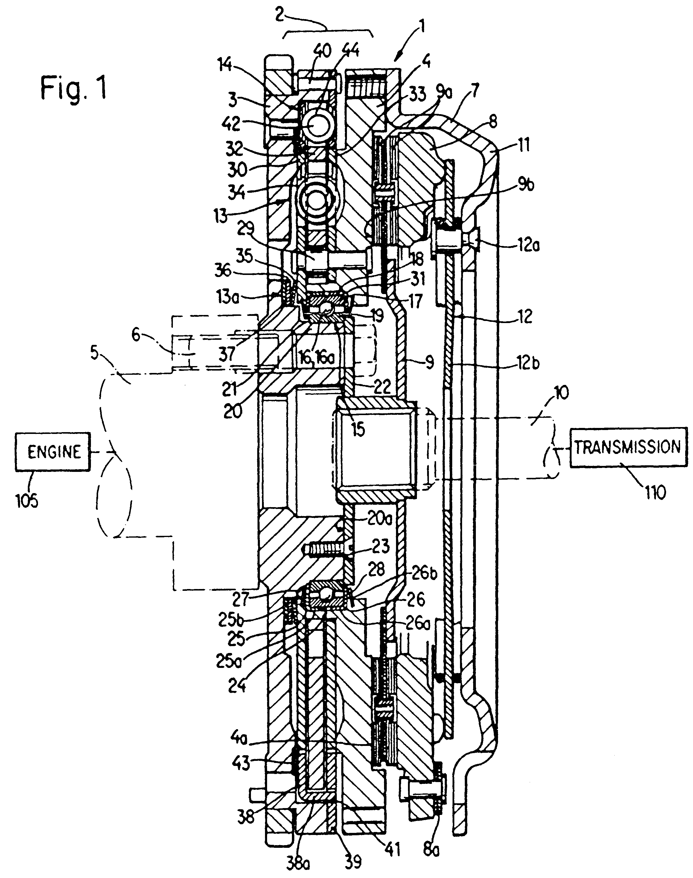
The torsion damping apparatus 1 of FIG. 1 comprises a composite flywheel 2 including a first flywheel 3 receiving torque from an internal combustion engine 105 by way of a crankshaft 5 which is secured thereto by an annulus of bolts 6 or analogous fasteners, and a second flywheel 4 which transmits torque to the input element 10 of a change-speed transmission 110 in a motor vehicle by way of a friction clutch 7. The friction clutch 7 comprises an axially shiftable pressure plate 8, an axially fixed pressure plate which constitutes the second flywheel 4, a clutch plate or disc 9 with two friction linings 9a, a cover or housing 11 and a diaphragm spring 12 which normally urges the pressure plate 8 against the adjacent lining 9a so that the friction- and heat-generating (second) surface 9b of the other lining 9a bears against the adjacent friction- and heat-generating (first) surface 4a of the flywheel 4. The diaphragm spring 12 is tiltably mounted between two wire-like ring-shaped seat...


PUM


Abstract

A torsion damping apparatus between the crankshaft of the engine and the input shaft of the change-speed transmission of a motor vehicle has two flywheels one of which is driven by the crankshaft and the other of which drives the input shaft by way of a friction clutch which generates heat. In order to prevent the transfer of heat from the friction clutch to the antifriction bearing between the flywheels, which are rotatable relative to each other against the opposition of a damper, the bearing is at least partially surrounded by a thermal barrier of synthetic plastic, ceramic or metallic material which prolongs the useful life of the bearing and enhances the torsion damping action of the damper. The thermal barrier can constitute or form part of the damper. The bearing can be disposed radially inwardly of the location of engagement between the clutch and the other flywheel and can be cooled by streams of air flowing through an annulus of passages each having a first end disposed radially inwardly of the friction surface of the other flywheel and a larger second end in a second surface of the other flywheel opposite the friction surface. Heat barriers in the other flywheel can alternate with the passages in the circumferential direction of the other flywheel.

Description

BACKGROUND OF THE INVENTIONThe present invention relates to torque transmitting and torsion damping apparatus, especially to improvements in torque transmitting and torsion damping apparatus which can be utilized in motor vehicles to compensate for fluctuations of torque which is transmitted between driving and driven components, particularly between the crankshaft of the internal combustion engine and the input shaft of the change-speed transmission in a passenger car or another motor vehicle.It is already known to provide a torsion damping apparatus, which is installed in a motor vehicle between the crankshaft of the internal combustion engine and the input shaft of the change-speed transmission, with several flywheels which are rotatable relative to each other within certain limits and against the opposition of one or more dampers. Such apparatus are disclosed, for example, in commonly owned copending patent application Ser. No. 669,657 of Oswald Friedmann as well as in several o...

Claims


Application Information

Patent Timeline
IPC IPC(8): F16F15/139F16F15/134F16C35/077F16C35/073F16C35/04F16F15/131
CPCF16C35/073F16C35/077F16F15/13164F16F15/13171F16F15/134F16F15/1397F16F2222/02F16F2222/025F16C2361/55F16C33/7886F16C19/06F16C27/066F16D2013/703
Inventor REIK, WOLFGANGELISON, HANS-DIETER
Owner LUK LAMELLEN & KUPPLUNGSBAU BETEILIGUNGS KG
Why Eureka
Try Eureka