
Switching voltage regulator circuit

a voltage regulator and switching voltage technology, applied in the direction of electric variable regulation, process and machine control, instruments, etc., can solve the problems of switching regulators that are more flexible than linear regulators in circuit applications, the isolation provided by the transformer between input and output circuits is limited, and the switching regulators are typically more complex than linear regulators. , to achieve the effect of simple implementation and efficient operation

Inactive Publication Date: 2006-04-18
ANALOG DEVICES INT UNLTD
View PDF66 Cites 24 Cited by
  • Summary
  • Abstract
  • Description
  • Claims
  • Application Information

AI Technical Summary

Benefits of technology

[0015]It is therefore an object of the present invention to provide an integrated circuit for use in implementing a switching voltage regulator circuit, the integrated circuit being simple to implement and capable of efficient operation in numerous switching regulator configurations.

Problems solved by technology

First, switching regulators typically operate with greater efficiency than linear regulators, a particularly important factor in high current regulators.
In either of the above transformer configurations, the isolation provided by the transformer between input and output circuits is limited by the need to regulate the output voltage by sensing the output voltage of the regulator circuit and providing a feedback voltage signal to the control circuitry of the circuit.
Switching regulators, although more flexible than linear regulators in circuit applications, are typically more complex than linear regulators.
Also, integrated circuits heretofore available typically required 8-14 terminals for connection to external discrete components, and could not be configured into a very low current (shutdown) mode.
This quantity of terminals prevented such integrated circuits from being packaged in low-cost power transistor packages such as the conventional 5-pin TO-3 type metal can or the TO-220 type molded plastic packages, and thus limited the power handling capability of the integrated circuit.
Further, heretofore available integrated circuits for use in implementing switching voltage regulators have not been capable of use both in normal feedback mode switching regulator circuits and isolated flyback mode regulator circuits.

Method used


Image

  • Switching voltage regulator circuit
  • Switching voltage regulator circuit
  • Switching voltage regulator circuit

Examples


Embodiment Construction

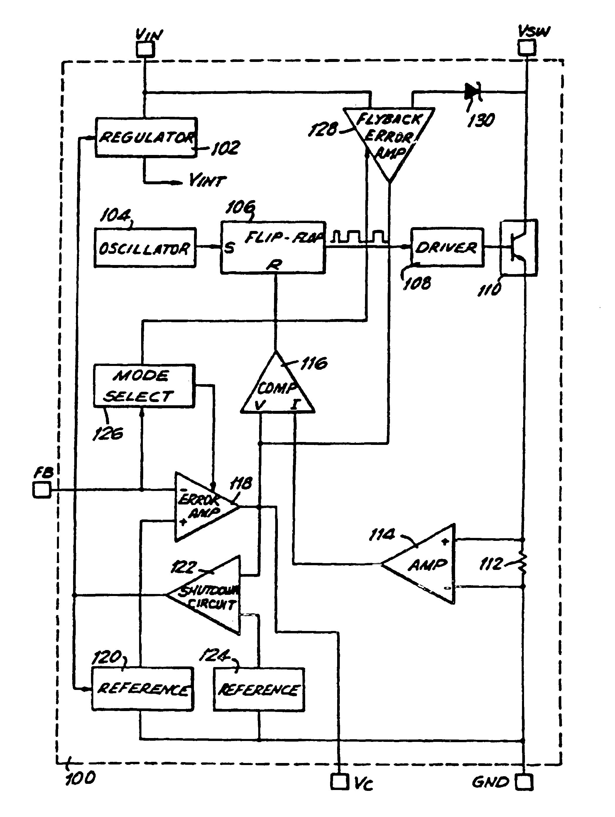
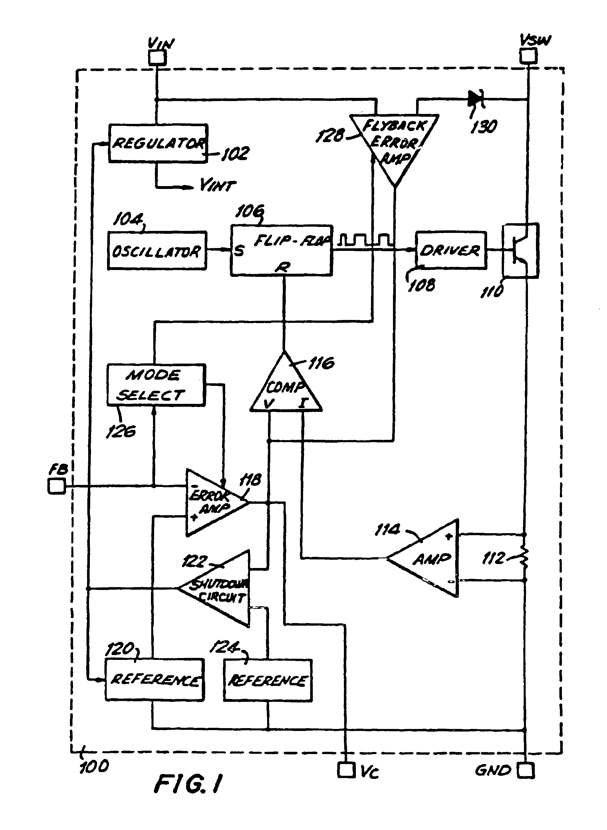
[0028]FIG. 1 shows a five-terminal integrated circuit 100 of the present invention capable of implementing a current-mode switching voltage regulator circuit, and capable of being packaged in a conventional 5-pin power package. Five terminals are shown, labeled as VIN (input supply), VSW (output), FB (feedback), VC (compensation) and GND (ground).

[0029]Terminal VIN provides a connecting point for input voltage, and is used to supply power to the internal circuitry of integrated circuit 100. Terminal VSW is the output terminal of circuit 100. It provides a connecting point between power switch 110 of regulator 100 and external components configured to implement a number of switching regulator topologies, to convert the pulsed current flowing through switch 110 into a regulated output voltage. Further, when regulator 100 is operated in an isolated flyback mode, as discussed further herein, terminal VSW provides a flyback reference voltage point which is held to a peak voltage level wh...


PUM


Abstract

An integrated circuit for use in implementing a switching voltage regulator, the integrated circuit including a power switching transistor, driver circuitry and control circuitry, which is operable in a normal feedback mode or an isolated flyback mode. The integrated circuit includes shutdown circuitry for placing the regulator in a micro-power sleep mode, and can be packaged in a five-pin conventional power transistor package. The terminals of the integrated circuit regulator perform multiple functions. A compensation terminal is used for frequency compensation, current limiting, soft-start operation and shutdown. A feedback terminal is used as a feedback input when the integrated circuit is in feedback mode, and as a logic pin to program the regulator for isolated flyback operation. The feedback terminal is also used to trim the flyback reference voltage.

Description

[0001]This is a continuation of application Ser. No. 08 / 558,204, filed Nov. 16, 1995, which is a continuation of application Ser. No. 07 / 683,549, filed Apr. 10, 1991, entitled Switching Voltage Regulator Circuit. [0002]This is a continuation of application Ser. No. 932,158, filed Nov. 18, 1986, entitled “SWITCHING VOLTAGE REGULATOR CIRCUIT”, now abandoned.BACKGROUND OF THE INVENTION[0003]The present invention relates to an integrated circuit switching voltage regulator circuit having multi-function terminals. More particularly, the present invention relates to an integrated circuit for use in implementing a switching voltage regulator circuit, the integrated circuit requiring only five terminals, operable in both feedback and isolated flyback mode, and including a power switching element, a driver network, and control circuitry which sets the duty cycle of the switching element.[0004]The function of a voltage regulator is to provide a predetermined and substantially constant output ...

Claims


Application Information

Patent Timeline
IPC IPC(8): G05F1/40H02M1/00H02M1/36H02M3/335
CPCH02M1/36H02M3/33507H02M3/33523Y02B70/10H02M1/0032
Inventor NELSON, CARL T.
Owner ANALOG DEVICES INT UNLTD
Learn More