
Termite control

a termite and chemical technology, applied in the direction of insect catchers and killers, power cables, structural elements, etc., can solve the problems of affecting the safety of people applying chemicals and other people in the vicinity, exposing them to the potential danger of chemicals used to control termites, and enduring danger afterward, so as to achieve convenient transportation and application, convenient work, and flexible

Inactive Publication Date: 2006-08-08
TMA CORP
View PDF59 Cites 9 Cited by
  • Summary
  • Abstract
  • Description
  • Claims
  • Application Information

AI Technical Summary

Benefits of technology

[0018]Alternatively the mesh may be embedded in one plastic sheet, preferably with both sides of the mesh sheet covered by the plastic material. The combining of the mesh sheet and the plastic provides protection of the mesh sheet against damage that may cause displacement of the strands forming the mesh, with resultant enlargement of the openings or pores of the mesh in a specific area thereof to a size to permit the passage of the termites therethrough.
[0019]It is also to be appreciated that it is normal practice to provide a sheet of plastic material beneath the concrete slab upon which a building is to be erected to provide a barrier against the entry of moisture through the concrete into the building. Accordingly, by incorporating the mesh sheet with or into a plastic sheet, the resulting assembly can perform the two functions of providing a moisture and a termite barrier.
[0029]The advantages of the termite barrier as proposed above are principally that there are no harmful chemicals used in the creation of the barrier, the barrier will have an effective life commensurate with the life of the building. Further, the barrier can be conveniently transported and applied without the level of precautions required when handling pesticides or other chemicals and with a minimum of skill. Further as the barrier is in the form of a mesh, it is substantially more flexible and easily worked as by cutting, contouring and shaping, particularly in comparison with solid sheet metal.BRIEF DESCRIPTION OF THE DRAWINGS

Problems solved by technology

These methods of termite control have the major disadvantage as the chemicals are usually of a composition that is considered highly dangerous to humans and thus constitute a hazard to the people applying the chemicals and to other people in the vicinity.
Thus people unaware of the presence of the chemicals, and thus not alerted to take protective action, may also be exposed to the potential danger of the chemicals used to control termites.
The danger continues to exist after the initial application of the chemical so long as the chemical remains effective against the termites.
This leaching will naturally reduce the effectiveness of the chemical as a barrier to the termites.
As the chemical in many instances is initially placed beneath a concrete slab upon which the building is erected, it is very difficult to apply further chemical to replace that removed by the leaching and so maintain an effective barrier.
Even more importantly, chemicals leached from the ground beneath the building are carried by the leaching water into other areas where it may be hazardous to humans, animals or crops.
Many buildings, particularly homes, are built on a slab of concrete and although termites can normally not penetrate concrete, cracks frequently develop in the concrete thus permitting the passage of termites therethrough into the building.
As the concrete is cast in situ about these pipes or conduits, a small opening often develops about the pipe or conduit due to shrinkage of the concrete during curing.
Although this may be effective and commercially viable in relation to a building supported on stumps, it is expensive and has installation problems when considered in respect to a building supported on a concrete slab.
Sheet metal is difficult to join on-site in a manner to exclude passage of termites through the joint.
Also, if the metal sheet is sufficiently strong to prevent accidental puncture by workman traffic on-site, it is then difficult to bend and shape to the required contours to fit with the building structure in a manner to provide an effective termite barrier.
It would also be difficult to achieve an effective seal around pipes or conduits that must pass through the sheet.
However, that sheet is preformed for a specific installation and is not appropriate for on-site construction to a range of shapes and configuration with the ability to maintain the integrity of a barrier against the passage of termites.

Method used


Image

  • Termite control
  • Termite control
  • Termite control

Examples


Embodiment Construction

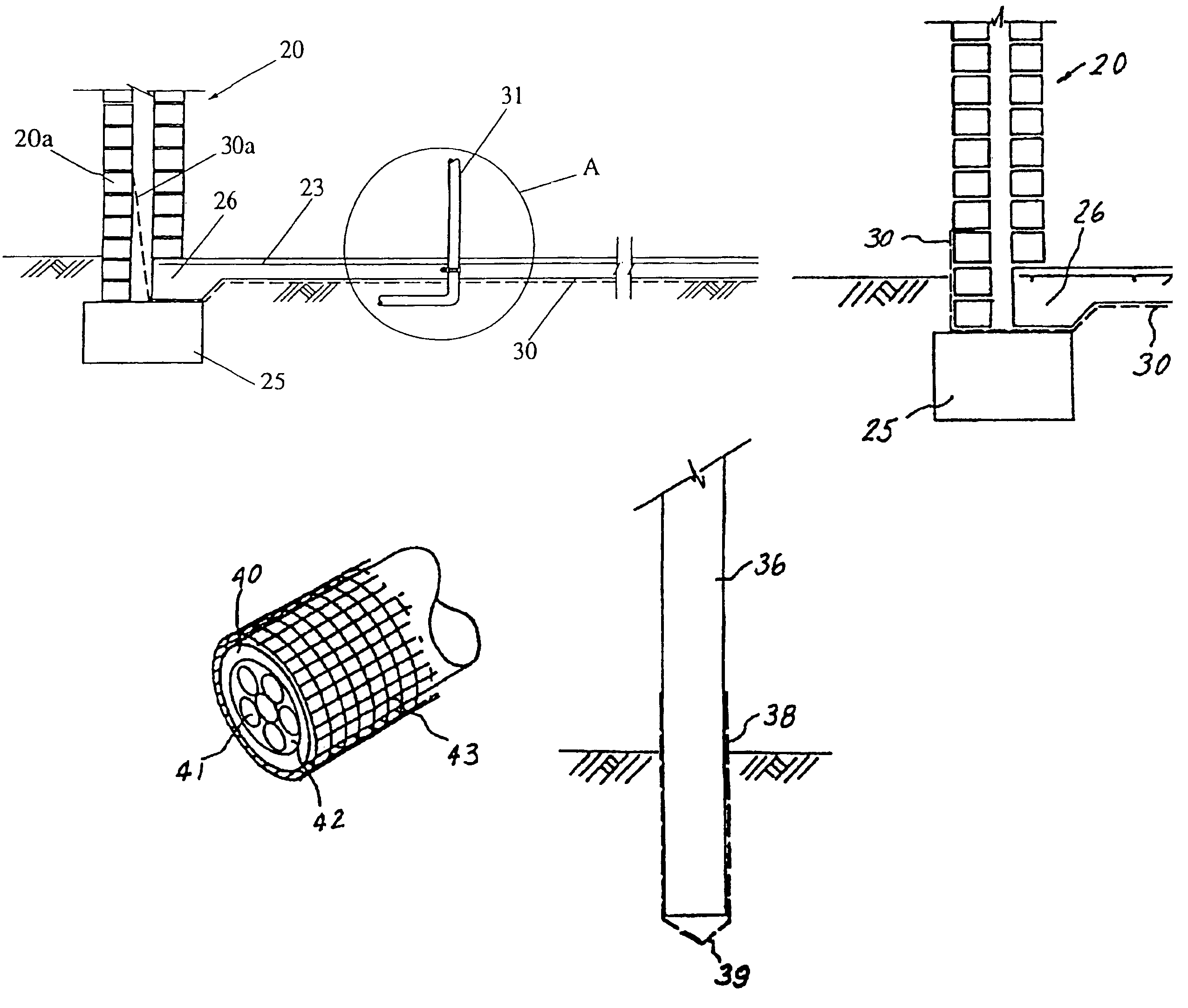
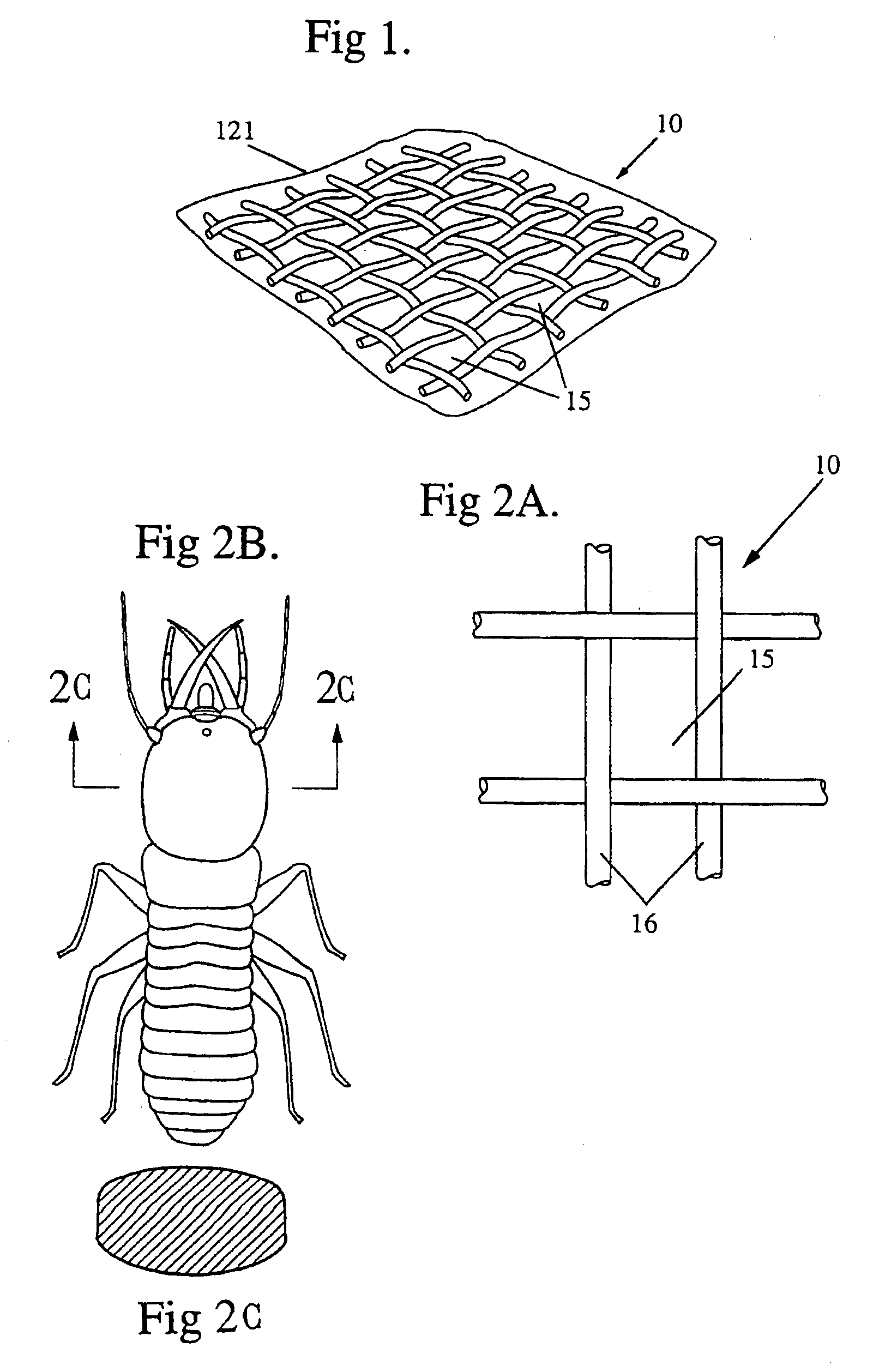
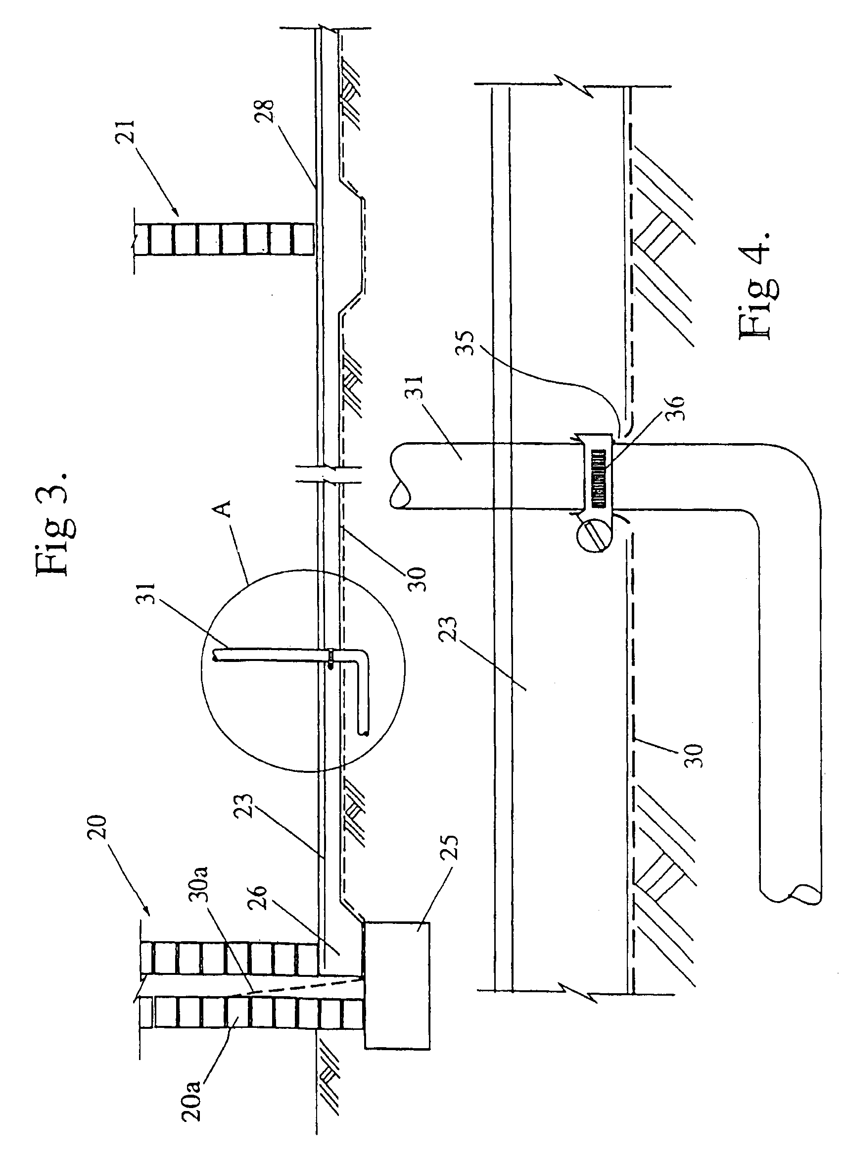
[0044]Referring now to FIGS. 1 and 2a-2c of the drawings, the termite barrier is in the form of a woven mesh 10 made of corrosion resistant stainless steel wires or filaments such as 304 grade stainless steel. The termite barrier may also include a flexible moisture impervious plastic sheet 121 formed to the woven mesh 10. Preferably, both sides of the woven mesh 10 are covered by a plastic sheet 121. The woven filaments form a series of pores or openings 15 in the mesh which are of a generally rectangular shape with the distance between the two more closely spaced sides 16 of the rectangle and the diagonal thereof is less than the maximum cross sectional dimensions of the head of the species of termite in respect of which the mesh is to form a barrier (FIG. 2c). For instance, the soldier termite of species Mastotermes darwiniensis, of northern Australia, has a maximum head width of 3.25 mm. To form a termite barrier for Mastotermes darwiniensis, the distance between the two more cl...


PUM

PropertyMeasurementUnit
lengthaaaaaaaaaa
lengthaaaaaaaaaa
diameteraaaaaaaaaa

Abstract

A barrier to termites particularly suitable for protecting buildings comprising a mesh made of a material that is resistant to breakdown in the environment of use and is resistant to secretions deposited by termites, such as stainless steel, and is also sufficiently hard to not be attacked by termites, such as having a hardness not less than about Shore D70. The pores of the mesh being dimensioned so the maximum linear dimension in any direction of the pores is less than the maximum linear dimension of the cross-section of the head of the species of termite to be controlled.

Description

[0001]This is a Continuation of U.S. Ser. No. 08 / 859,561, filed May 20, 1997, which is a Reissue Application of U.S. Pat. No. 5,417,017, which issued May 23, 1995 from U.S. Ser. No. 08 / 040,305, filed Mar. 30, 1993, which is a Continuation-in-Part application of U.S. Ser. Nos. 07 / 575,908, filed Aug. 31, 1990, now abandoned, and 07 / 825,299, filed Jan. 23, 1992, now abandoned.BACKGROUND OF THE INVENTION[0002]This invention relates to the control of termites in relation to buildings and other structures and in particular to achieving such control without the use of harmful chemicals.[0003]The most popular procedure for providing a barrier to the access of termites to buildings or other structures supported in or on the ground is to saturate the ground beneath or around the structure with appropriate chemicals, to kill any existing termites, and to provide a residue of the chemical within the ground which will remain effective for many years against the passage of termites therethrough t...

Claims


Application Information

Patent Timeline
Patent Type & Authority Patents(United States)
IPC IPC(8): A01M1/00E04B1/72
CPCA01M1/24A01M29/34E04B1/72
Inventor TOUTOUNTZIS, VASILIOS
Owner TMA CORP
Learn More