Al technical title is built by PatSnap Al team. It summarizes the technical point description of the patent document.
a cleaning machine and upright technology, applied in the direction of valve operating means/release devices, carpet cleaners, detergent compounding agents, etc., can solve the problems of inconvenient cleaning solution inclusion of detergents and the like in the cleaning solution, the inability to simply convert the current upright extraction cleaning machine, and the inability to fill and empty the fluid supply chamber and the fluid recovery chamber
Inactive Publication Date: 2006-09-26
BISSELL HOMECARE
View PDF90 Cites 43 Cited by
Summary
Abstract
Description
Claims
Application Information
AI Technical Summary
This helps you quickly interpret patents by identifying the three key elements:
Problems solved by technology
Method used
Benefits of technology
Problems solved by technology
Another problem inherent with the known extraction cleaning machines is the difficulty of filling and emptying the fluid supply chamber and fluid recovery chamber, particularly with bladder-within-a-tank type assemblies.
Further, none of the current upright extraction cleaning machines are simply convertible to a pre-spray applicator for directing cleaning solution to and agitating the surface to be cleaned without applying suction.
Because the steam is airborne, it may be unsafe to include detergents and the like in the cleaning solution.
Further, while the steam systems have the advantage of creating a temperature that effectively kills a wider range of microbes, bacteria, microorganisms, and mites, the steam systems generally suffer from poor cleaning performance.
Additionally, the high power requirement for generating steam may not be sufficient with ordinary 120V power supplies for running a vacuum motor as well as the steam generator, so cleaning performance is further hindered.
Also, by adding a heater to a fluid supply chamber, the user may be inconvenienced by the amount of time required to heat the contents of the supply chamber to the desired temperature.
Method used
Image
Click on the blue label to locate the original text in one second.
Reading with bidirectional positioning of images and text.
Examples
Embodiment Construction
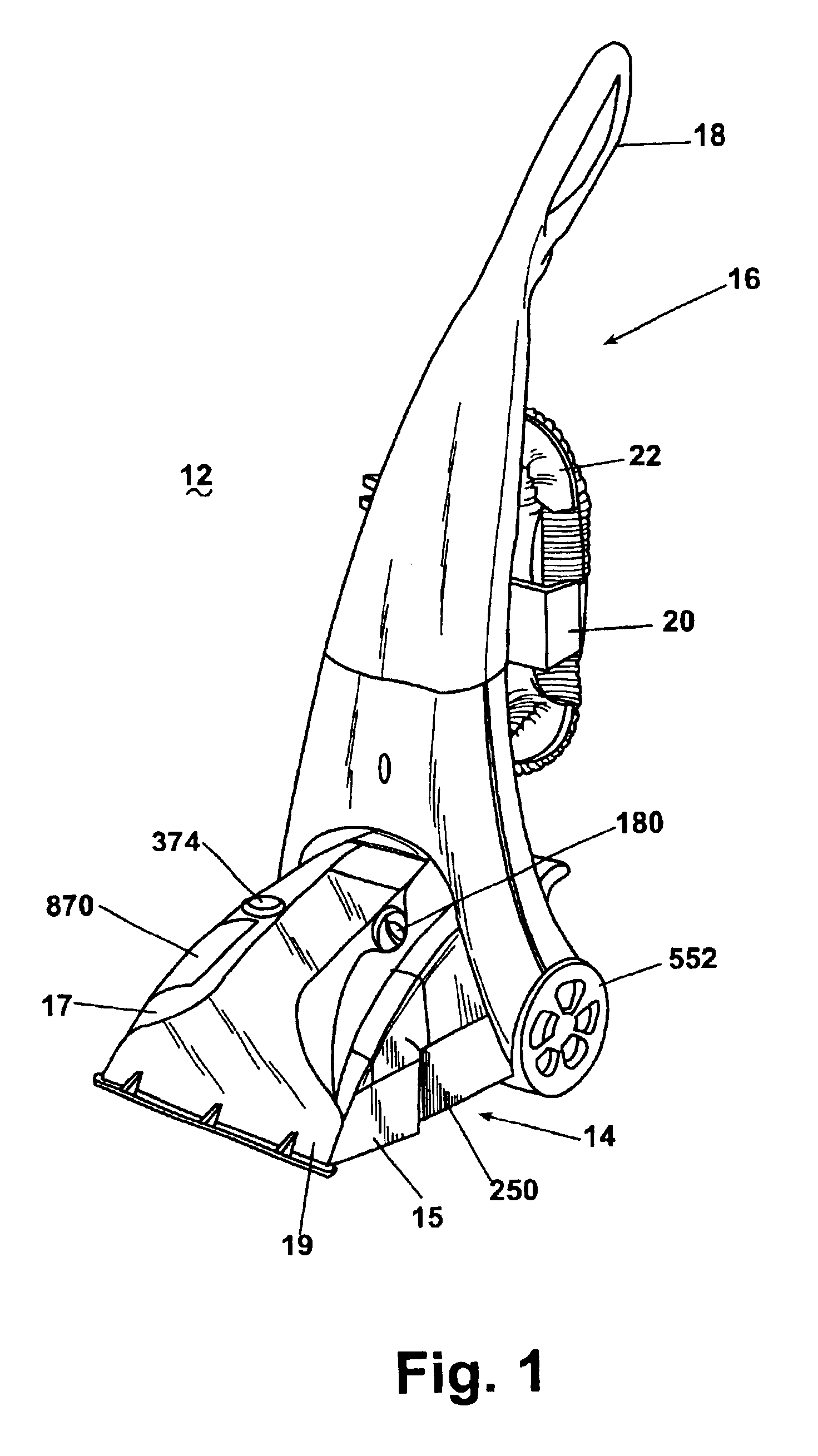
[0047]Referring now to the drawings and to FIG. 1 in particular, an upright extraction cleaning machine 12 according to the invention is shown. The machine 12 is a portable surface cleaning apparatus including a base module 14 adapted to roll across a surface to be cleaned and an upright handle assembly 16 pivotably mounted to a rear portion of the base module 14.
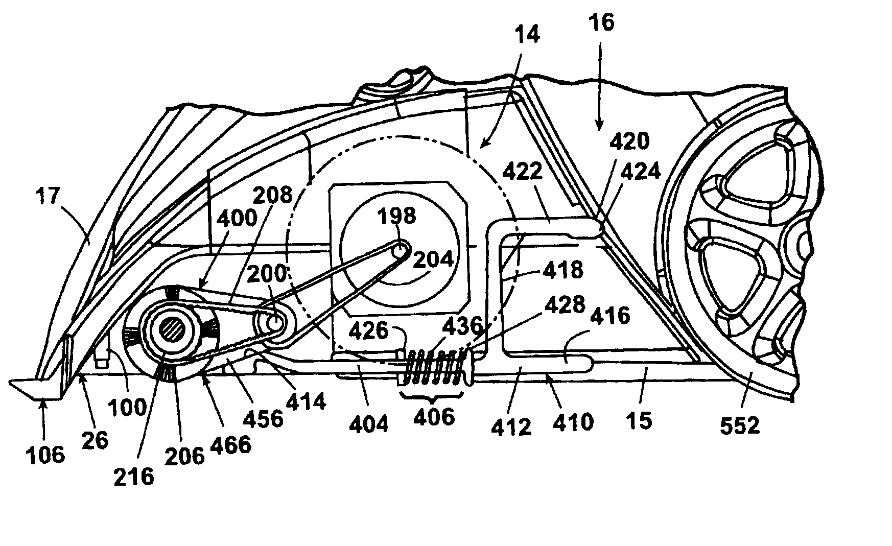
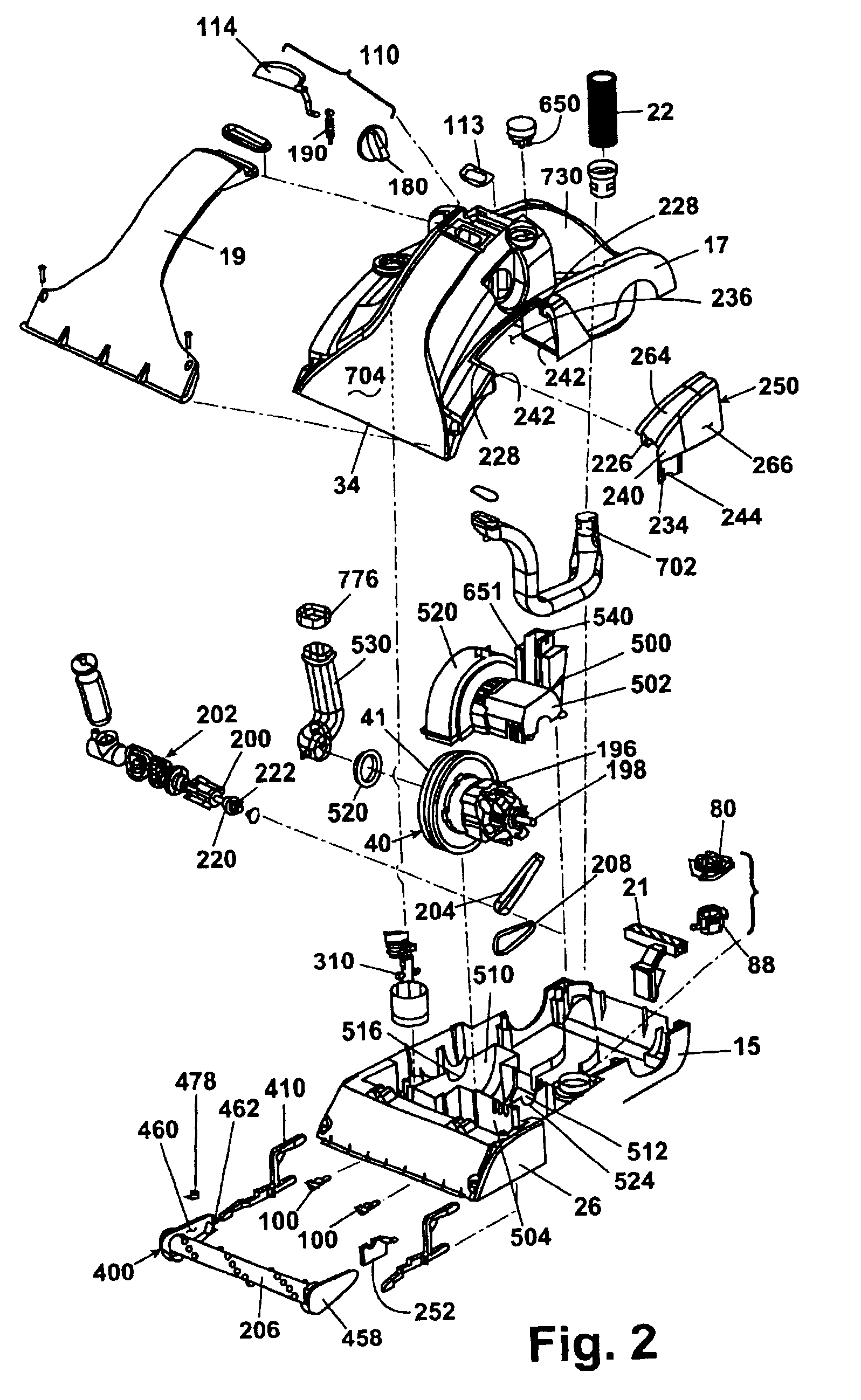
[0048]As best shown in FIGS. 1-3, the base module 14 includes a lower housing portion 15 and an upper housing portion 17, which together define an interior for housing components and a well 730 for receiving a tank assembly 50. Further, a well 732 in the upper housing portion 17 receives a detergent supply tank 870, as best shown in FIG. 3. The upper housing portion 17 receives a transparent facing 19 for defining a first working air conduit 704 and a suction nozzle 34, which is disposed at a front portion of the base module 14 adjacent the surface being cleaned for recovering fluid therefrom. The handle assembly 16 has a c...
PUM
Property
Measurement
Unit
volume
aaaaa
aaaaa
temperature
aaaaa
aaaaa
surface heights
aaaaa
aaaaa
Abstract
A portable surface cleaning apparatus including a base module for movement along a surface , an upright handle pivotally attached to the base module, a liquid dispensing system including a flexible bladder defining a fluid supply chamber for holding a supply of cleaning fluid , a fluid recovery system including a tank on the base module having a fluid recovery chamber for holding recovered fluid and housing the flexible bladder, and a fluid passageway between the fluid supply chamber and the recovery chamber, whereby the recovery chamber is in fluid communication with the fluid supply chamber and the pressure in the flexible bladder is equalized with the pressure in the tank as the cleaning fluid is dispensed from the supply chamber and the dirty liquid is collected in the recovery chamber. In a further embodiment the tank has an outlet opening in a bottom portion thereof and a drain plug is removably mounted in the outlet opening. In another embodiment a lid mounted on the tank defines an expansion chamber having an inlet opening, an outlet passage, and first and second diverters against which the working air flow reverses direction twice between the inlet opening of the expansion chamber and the tank. In another embodiment the working air conduit includes a manual actuator knob having an over-center linkage mechanism connected to a conversion valve for movement between first and second positions and thereby selectively moving the conversion valve between open and closed positions, whereby fluid communication between the tank and the suction nozzle is selectively opened and closed. In a further embodiment, a flow indicator is mounted to the base module and has a visibility window observable to a user and the flow indicator is disposed in the fluid supply conduit and is responsive to the flow of fluid through the fluid supply conduit to visually indicate the flow of fluid through the supply conduit to the user. Another embodiment includes a pump primer connected to the pump and having a housing defining a priming chamber with a valved opening connected to the vacuum source, an inlet opening connected to the fluid supply chamber, and an outlet opening connected to an inlet for the pump. A further embodiment includes a first mechanical connector extending between the motor drive shaft and the pump drive shaft, whereby the motor drives both the agitation brush and the pump. In a further embodiment, the base module includes an upper housing portion and a lower housing portion and an upright handle is pivotably mounted to the rear portion of the base module through at least one bearing for rotatable reception in the housing. In another embodiment , an elevator assembly is reciprocally mounted to the base module and movable in response to movement of the upright handle from an operative position to the upright position for upwardly pivoting a pivot arm mounting an agitation brush.
Description
CROSS REFERENCE TO RELATED APPLICATIONS[0001]This application is a divisional application of U.S. patent application Ser. No. 09 / 112,527, filed Jul. 8, 1998, now U.S. Pat. No. 6,167,587, issued Jan. 2, 2001, which claims the benefit of U.S. Provisional Application Serial No. 60 / 075,924, filed on Feb. 25, 1998, and U.S. Provisional Application Serial No. 60 / 052,021, filed on Jul. 9, 1997.BACKGROUND OF THE INVENTION[0002]1. Field of the Invention[0003]This invention relates to an extraction cleaning machine and, more particularly, to an upright extraction cleaning machine.[0004]2. Description of Related Art[0005]Upright extraction cleaning machines have been used for removing dirt from surfaces such as carpeting, upholstery, drapes and the like. The known extraction cleaning machines can be in the form of a canister-type unit as disclosed in U.S. Pat. No. 5,237,720 to Blase et al. or an upright unit as disclosed in U.S. Pat. No. 5,500,977 to McAllise et al. and U.S. Pat. No. 4,559,665...
Claims
Application Information
Patent Timeline
Application Date:The date an application was filed.
Publication Date:The date a patent or application was officially published.
First Publication Date:The earliest publication date of a patent with the same application number.
Issue Date:Publication date of the patent grant document.
PCT Entry Date:The Entry date of PCT National Phase.
Estimated Expiry Date:The statutory expiry date of a patent right according to the Patent Law, and it is the longest term of protection that the patent right can achieve without the termination of the patent right due to other reasons(Term extension factor has been taken into account ).
Invalid Date:Actual expiry date is based on effective date or publication date of legal transaction data of invalid patent.