Method of fabricating Bragg gratings using a silica glass phase grating mask and mask used by same

a technology of phase grating and bragg grating, which is applied in the field of optical media, can solve the problems of low writing efficiency, high spatial and temporal coherence of laser sources, and gratings with a period similar to that of one half the wavelength of writing light,

Inactive Publication Date: 2007-10-02
HER MAJESTY THE QUEEN & RIGHT OF CANADA REPRESENTED BY THE MIN OF COMM
View PDF27 Cites 8 Cited by
  • Summary
  • Abstract
  • Description
  • Claims
  • Application Information

AI Technical Summary

Benefits of technology

[0011]In the present invention the index grating is imprinted in the core of the optical fiber using a specially designed silica glass phase grating mask. The phase mask is held in close proximity to

Problems solved by technology

The principal drawbacks of the grating fabrication technique described in the first patent is that only gratings with a period similar to that of one half the wavelength of the writing light can be made.
However, the technique requires an ultraviolet laser source with a high degree of spatial and temporal coherence.
Such laser sources are research lasers that are expensive, have low writing efficiencies and are not suitable for us

Method used


Image

  • Method of fabricating Bragg gratings using a silica glass phase grating mask and mask used by same
  • Method of fabricating Bragg gratings using a silica glass phase grating mask and mask used by same
  • Method of fabricating Bragg gratings using a silica glass phase grating mask and mask used by same

Examples


Embodiment Construction

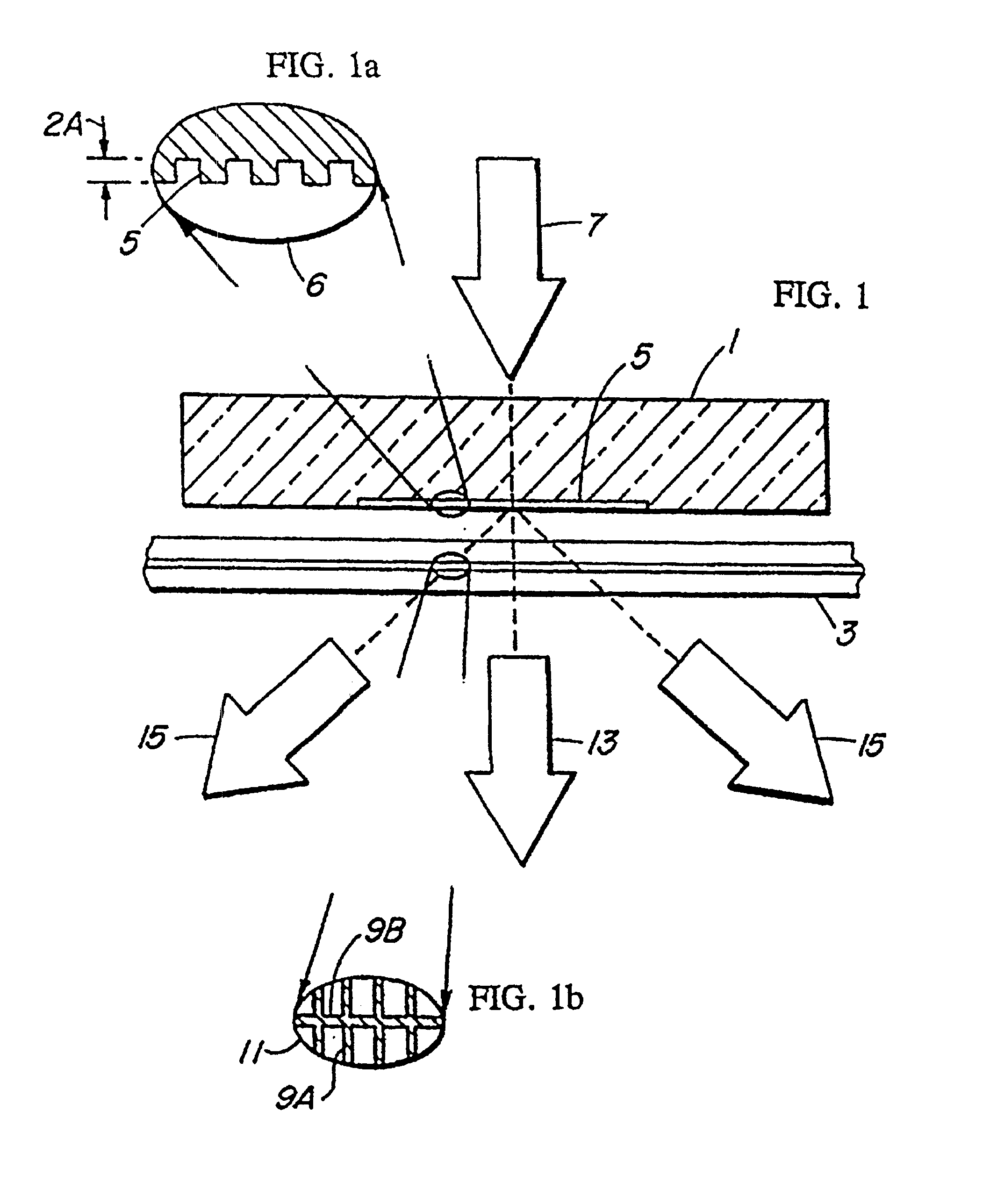
[0020]A phase grating slit-mask 1 is used in a precision photolithographic apparatus and is placed in contact, or near-contact, with an optical fiber 3, its grating striations 5 (as illustrated in magnification 6 of the mask) directed normal or near normal to the fiber axis. A UV light beam 7 from a suitable laser, a KrF excimer laser (249 nm) in a successful prototype is passed through the mask 1 by which it is phase modulated spatially and is diffracted to form an interference pattern 9A laterally (Bragg grating pitch) and along the incident laser beam direction 9B (Talbot pitch) as illustrated in magnification 11 of the core of the fiber.

[0021]The slit-mask preferably is comprised of a one dimensional surface-relief structure as shown at 6 fabricated in a high quality fused silica flat transparent to the KrF excimer laser radiation. The shape of the periodic surface-relief pattern of the phase mask preferably approximates a square wave in profile, as shown at 6. The amplitude of ...


PUM


Abstract

An index grating is imprinted in the core of an optical fiber using a specially designed silica glass phase grating mask. The phase mask is held in close proximity to the optical fiber. Laser irradiation of the phase mask with ultraviolet light at normal incidence imprints (photoinduces) into the optical fiber core the interference pattern created by the phase mask.

Description

CROSS REFERENCE TO RELATED APPLICATION[0001]This application is a continuation-in-part application of U.S. application Ser. No. 07 / 811,299, filed Dec. 20, 1991, now U.S. Pat. No. 5,216,739 which is a continuation-in-part application of U.S. application Ser. No. 07 / 656,462, filed Feb. 19, 1991, now U.S. Pat. No. 5,104,209.<?insert-end id="INS-S-00001" ?>FIELD OF THE INVENTION[0002]This invention relates to optical media such as optical fibers, and particularly to a method for fabricating Bragg gratings-therein.BACKGROUND TO THE INVENTION[0003]Certain optical fiber waveguides exhibit the property of photosensitivity which provides a practical means for photoinducing permanent refractive index changes in the core of those fibers. Photosensitivity is not restricted to fiber structures: it has also been detected in several types of planar glass structures, including, for example, silica-on-silicon and ion-implanted silica waveguides devices.[0004]The fabrication of optical waveguid...

Claims


Application Information

Patent Timeline
IPC IPC(8): G02B6/34G02B6/12H01L31/18G02B6/14
CPCG02B6/02047G02B6/02085G02B6/02147G02B6/14Y02P70/50G02B5/1857
Inventor HILL, KENNETH O.MALO, BERNARD Y.BILODEAU, FRANCOIS C.JOHNSON, DERWYN C.
Owner HER MAJESTY THE QUEEN & RIGHT OF CANADA REPRESENTED BY THE MIN OF COMM
Why Eureka
Try Eureka