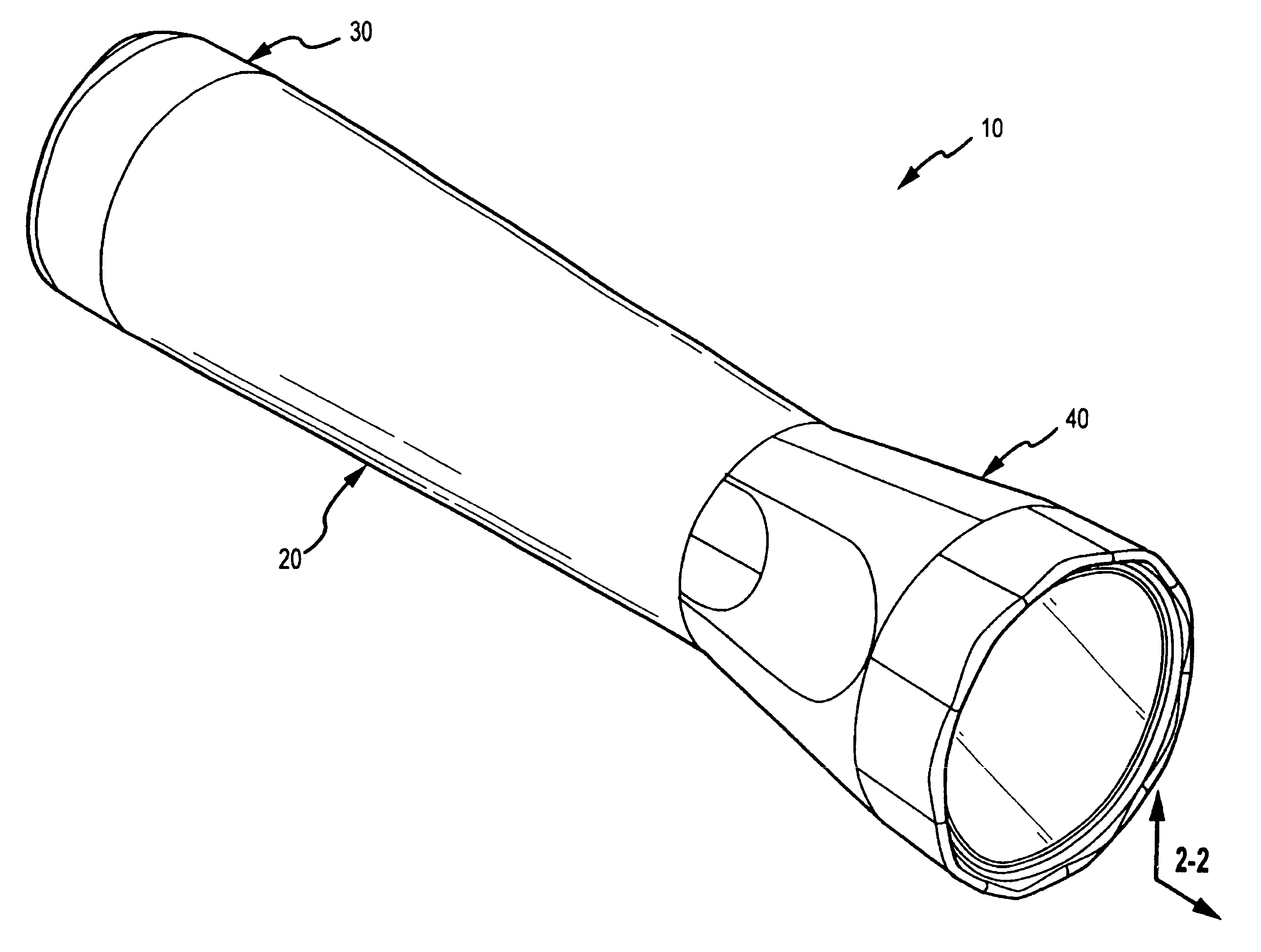
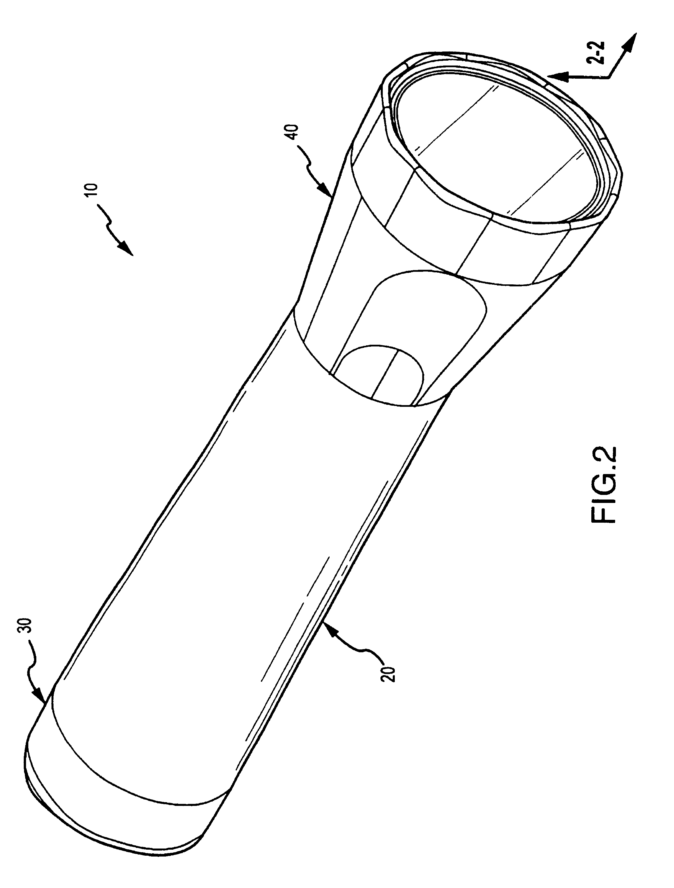
Tubular barrel-shaped flashlight having rotatable switching assembly and focusing and defocusing capability
- Summary
- Abstract
- Description
- Claims
- Application Information
AI Technical Summary
Benefits of technology
Problems solved by technology
Method used
Image

Examples
first embodiment
[0057]The lamp holder assembly 50 includes two embodiments. In either embodiment, the lamp holder assembly 50 is positioned at the second end 220 of the chamber 20. In the first embodiment, the lamp holder assembly 50 does not move inside the second end 220 of the chamber 20 when the flashlight 10 is turned “off” or “on.” In this regard and referring to FIGS. 8A and 8B, the lamp holder assembly 50 includes a lamp holder 510, a conductive spring 520, a switch lever 530, a second lever 540, a switch spring 550, a switch contact 560, a second spring 570, a spring holder 580, a conductive strip 590 and a strip support 592. The spring holder 580 includes a spring tab 582, first tab 584, second tab 586, and a first conductive contact 588. Preferably, the spring holder 580 includes a notch 589 wherein a hydrogen catalyst can be placed to absorb hydrogen gas emitted by the batteries 60, 62. As shown in FIG. 10, when assembled to the chamber 20, the lamp holder assembly 50 does not extend be...
second embodiment
[0068]As indicated above and with reference to FIGS. 16-27, the lamp holder assembly 50 includes a second embodiment, the lamp holder assembly 500, which moves inside the second end 220 of the chamber 20 when the flashlight 10 is turned “off” or “on.” Referencing FIG. 20, the lamp holder assembly 500 includes a lamp holder 610, a conductive spring 620, a switch plate 630, a detent lever 640, a detent ball 650, a switch contact 660, a spring contact 670, a conductive strip 690, and a strip support 692. The lamp holder assembly 500 is assembled to the chamber 20 by first attaching the conductive spring 620 to the lamp holder 610. The lamp holder 610 includes a spring tab (not shown) which engages and retains a portion of the conductive spring 690 and holds the conductive spring 690 in contact with the spring contact 670, as is shown in FIG. 21. The lamp holder 610 and attached conductive spring are next positioned at the second end 220 of the chamber 20. Referencing FIG. 18, the lamp ...
PUM
 Abstract
Description
Claims
Application Information
 - R&D Engineer
- R&D Manager
- IP Professional
- Industry Leading Data Capabilities
- Powerful AI technology
- Patent DNA Extraction
Browse by: Latest US Patents, China's latest patents, Technical Efficacy Thesaurus, Application Domain, Technology Topic.
© 2024 PatSnap. All rights reserved.Legal|Privacy policy|Modern Slavery Act Transparency Statement|Sitemap