Orthopaedic fixation plate

a technology for orthopaedic fixation and plate, which is applied in the field of plate, can solve the problems of complex construction and use, many parts of the frame, etc., and achieve the effect of facilitating the unique method of using the taylor spatial frameTM fixator

Inactive Publication Date: 2009-09-08
SMITH & NEPHEW INC
View PDF69 Cites 81 Cited by
  • Summary
  • Abstract
  • Description
  • Claims
  • Application Information

AI Technical Summary

Benefits of technology

[0009]It is an object of the present invention to provide a novel external fixation plate that can be used as part

Problems solved by technology

The Ilizarov system provides an external fixation frame that allows for gradual correction along and about six axes; however such frames require many parts and are relatively complicated to build and use in a clinical sit

Method used


Image

  • Orthopaedic fixation plate
  • Orthopaedic fixation plate
  • Orthopaedic fixation plate

Examples


Embodiment Construction

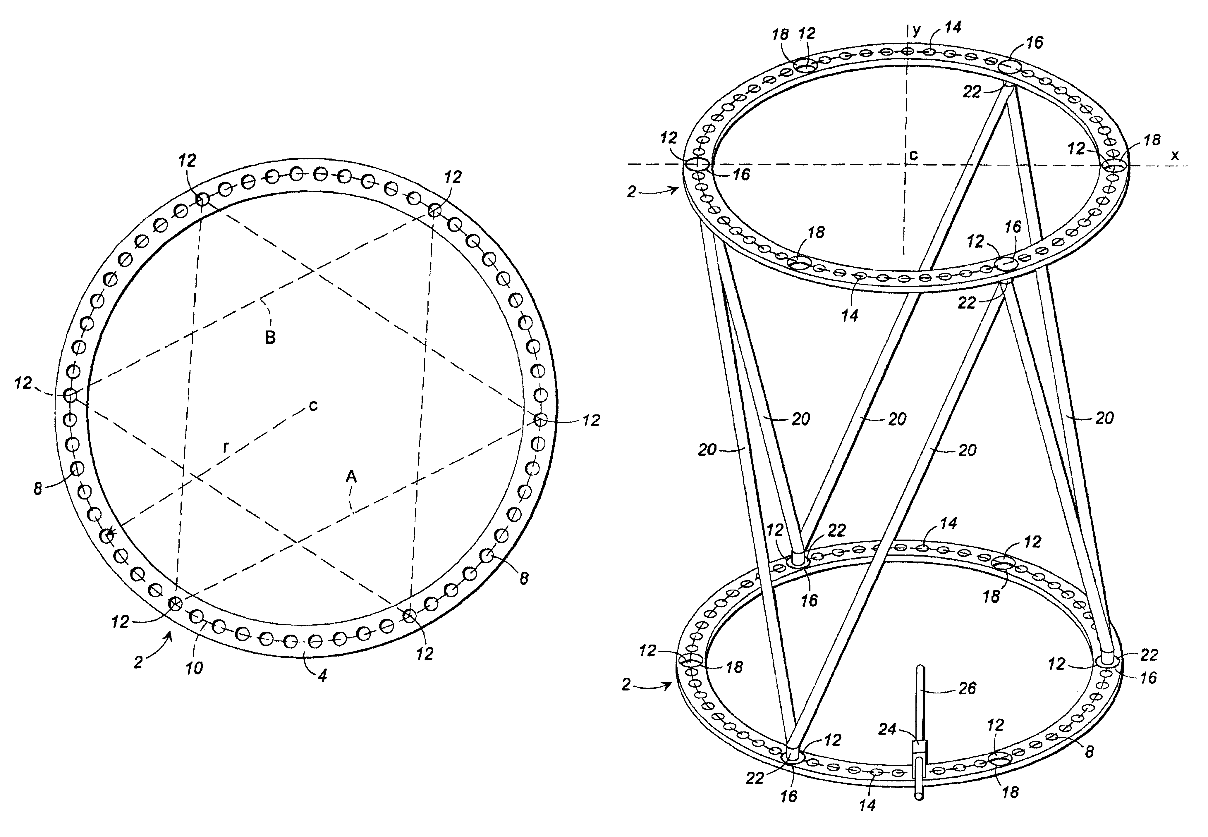
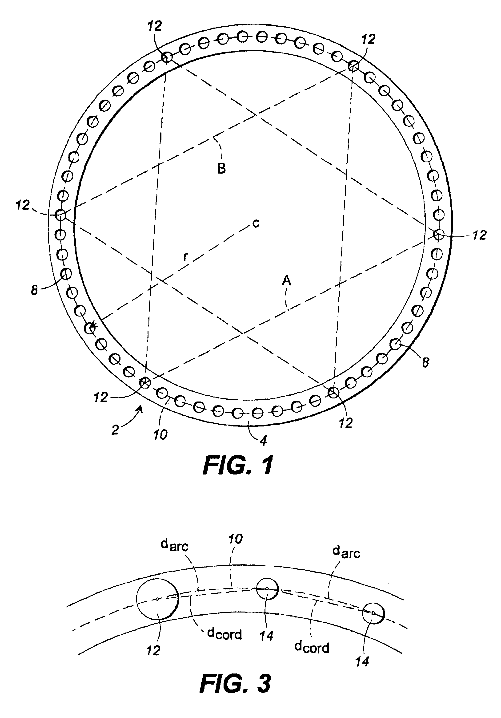
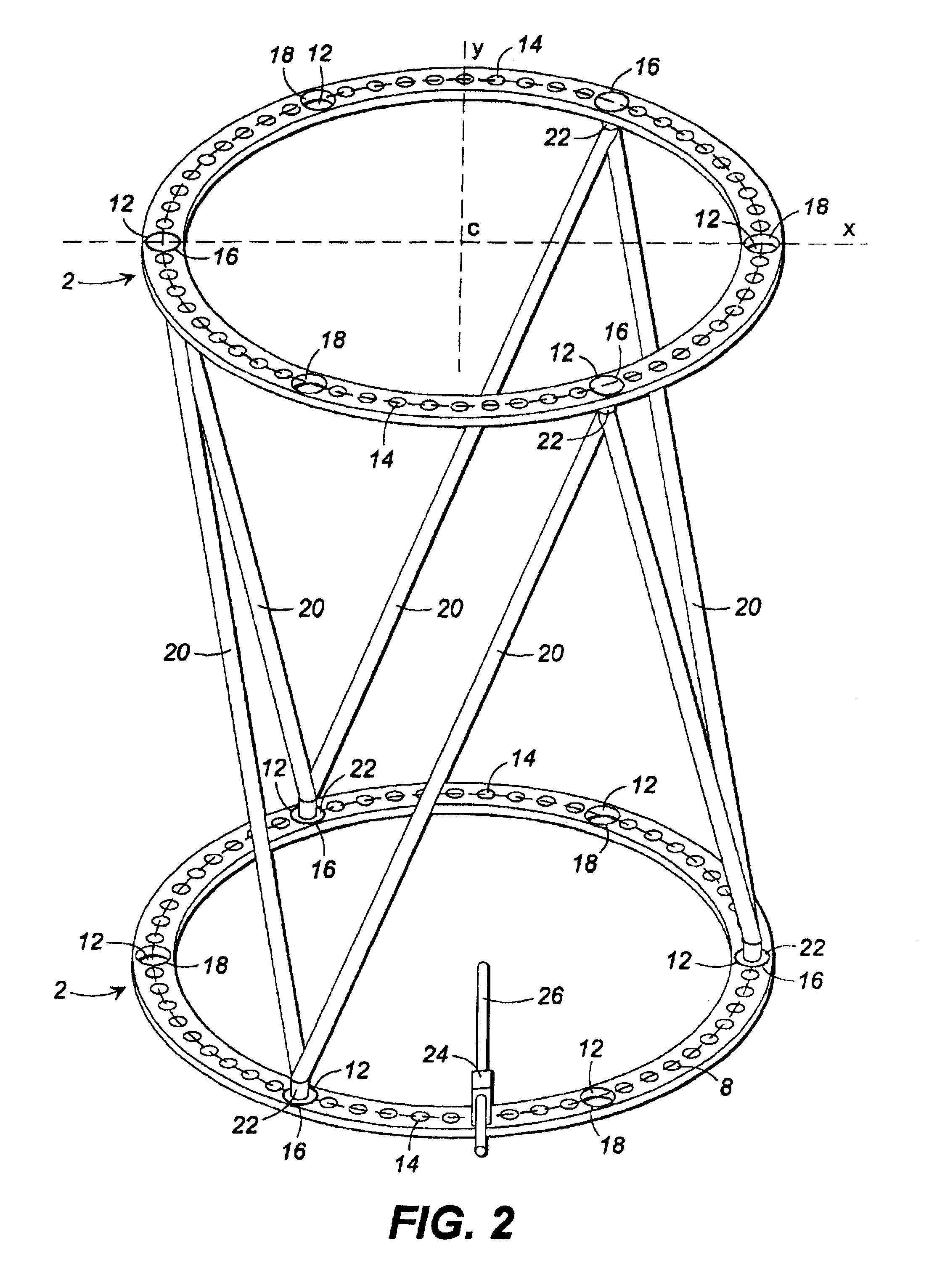
[0026]Because of the unique nature of the Taylor Spatial FRAME™ fixator and the unique method of using the Taylor Spatial FRAME™ fixator, the position of a given hole relative to another hole, either on the same plate or a different plate, is very important. Indeed, we have found that the correct positioning of the holes simplifies the manufacturing and device construction processes, simplifies the method of using the device by simplifying the geometric analysis of the system, and provides a number of clinical advantages.

[0027]FIG. 1 illustrates a fixator plate in accordance with a preferred embodiment of the present invention. The plate 2 includes a circuit body portion 4 fabricated from a suitably strong and rigid material such as a metal, alloy, plastic, composite, or ceramic. The body portion 4 includes a plurality of substantially equally spaced apertures or holes 8 positioned arcuately therein. In the specific embodiment shown in FIG. 1, the center of the holes 8 form a comple...


PUM


Abstract

A plate for use in fixating the position of a first bone segment relative to a second bone segment, the plate comprising a body portion having a plurality of attachment mechanisms located therein, wherein the attachment mechanisms include: a first group of three attachment mechanisms substantially positioned within 90°-150° of one another about a circle, and preferably within substantially 120° of one another, whereby the first group of attachment mechanisms is designed to facilitate attachment of a plurality of adjustable length struts to the plate; and a second group of attachment mechanisms substantially positioned about the circle that are designed to facilitate attachment of accessories to the plate, wherein the total number of the attachment mechanisms is a multiple of three.

Description

BACKGROUND OF THE INVENTION[0001]1. Field of the Invention[0002]The present invention relates to a plate for use as part of an external fixation device, and more particularly to a unique hole pattern within the plate.[0003]2. General Background and Description of the Prior Art[0004]Traditional circular ring external fixation devices consist of Ilizarov-type devices that are based on a circumferential external fixator system disclosed by G. A. Ilizarov during the early 1950's. The Ilizarov system includes at least two rings or “halos” that encircle a patient's body member (e.g., a patient's leg), connecting rods extending between the two rings, transfixion pins that extend through the patient's boney structure, and connectors for connecting the transfixion pins to the rings. Use of the Ilizarov system to deal with angulation, translation and rotation is disclosed in “Basic Ilizarov Techniques,” Techniques in Orthopaedics®, Vol. 5, Nov. 4, December 1990, pages 55-59.[0005]The Ilizarov...

Claims


Application Information

Patent Timeline
IPC IPC(8): A61B17/56A61B17/62A61B17/66
CPCA61B17/62A61B17/66
Inventor TAYLOR, J. CHARLESTAYLOR, HAROLD S
Owner SMITH & NEPHEW INC
Why Eureka
Try Eureka