
Tandem compressors with discharge valve on connecting lines

a technology of connecting line and discharge valve, which is applied in the direction of positive displacement liquid engine, lighting and heating apparatus, heating types, etc., can solve the problems of substantial leakage loss, reduced system performance, and insufficient fluid tightness of check valves to prevent leakage, etc., and achieve the effect of eliminating leakage losses

Inactive Publication Date: 2011-11-29
CARRIER CORP
View PDF7 Cites 0 Cited by
  • Summary
  • Abstract
  • Description
  • Claims
  • Application Information

AI Technical Summary

Benefits of technology

The solution effectively reduces refrigerant leakage, maintains system performance, and prevents fluid migration, ensuring efficient operation and preventing compressor flooding during startup.

Problems solved by technology

While the compressors are typically provided with a discharge check valve within the compressor shell, such check valves typically are not tight enough to prevent such leakage.
Further, under high pressure differential, such check valves may distort and become even less fluid-tight, or malfunction.
Thus, the prior art tandem compressors, even the ones with check valves within the compressor shell can have substantial leakage losses and subsequent system performance degradation.

Method used


Image

  • Tandem compressors with discharge valve on connecting lines
  • Tandem compressors with discharge valve on connecting lines
  • Tandem compressors with discharge valve on connecting lines

Examples


Embodiment Construction

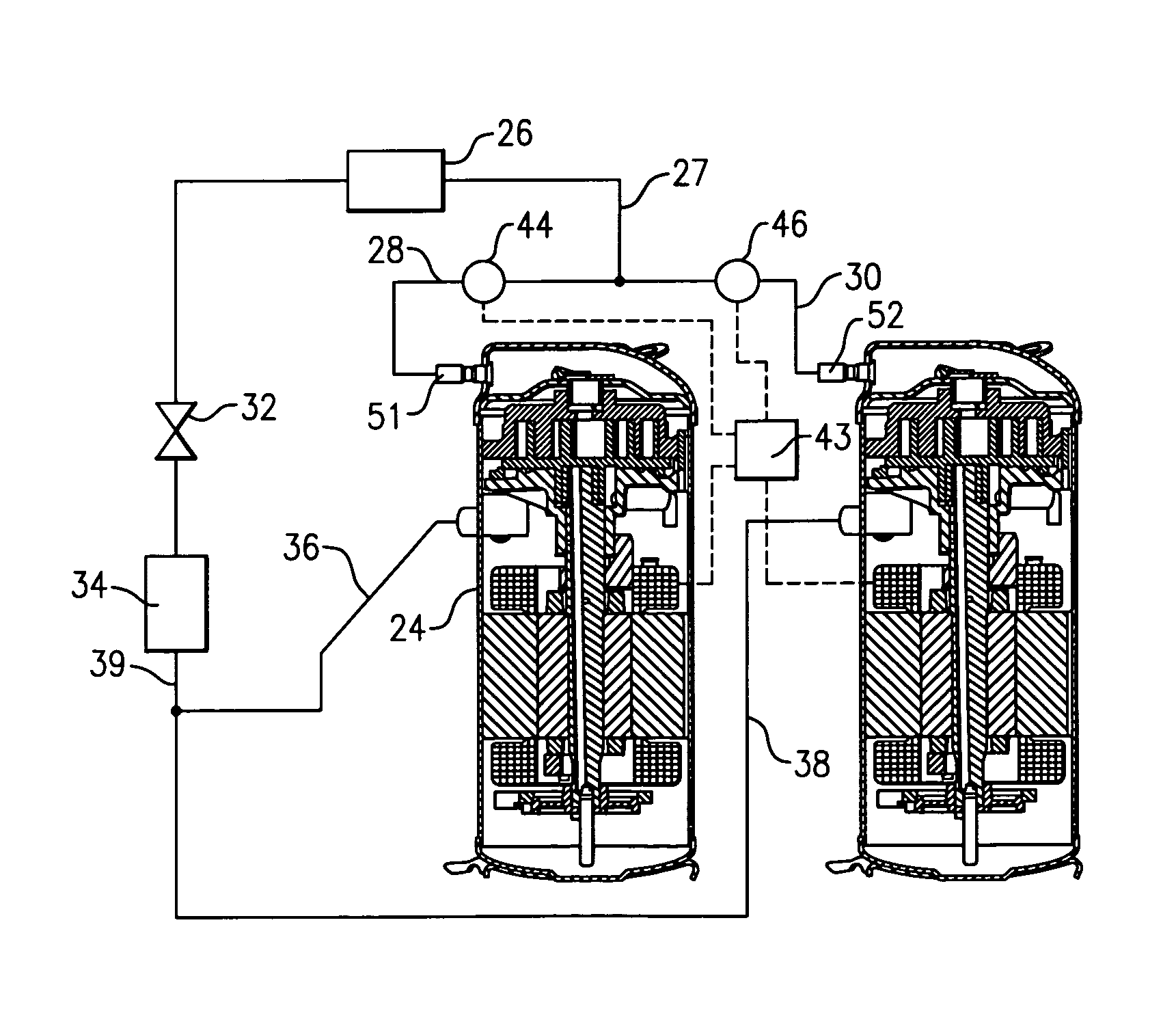
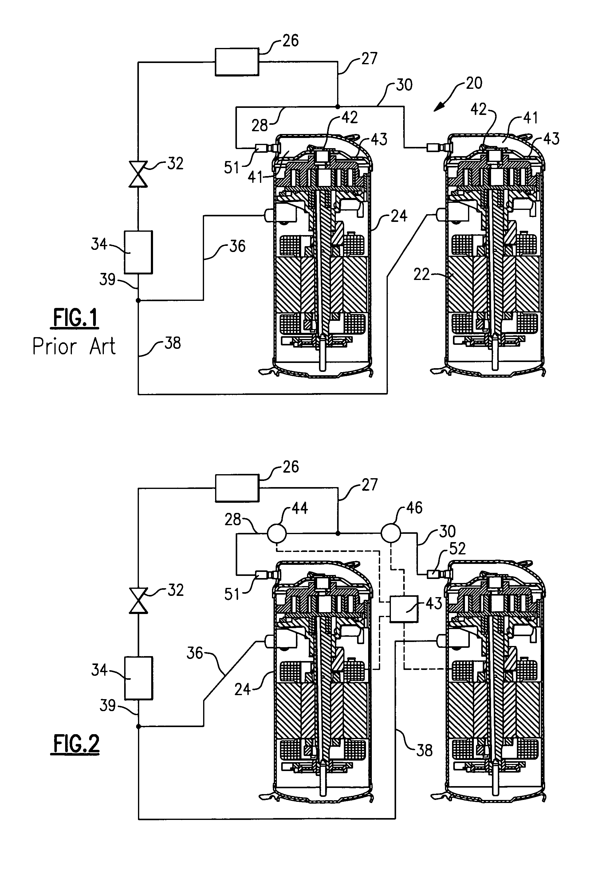
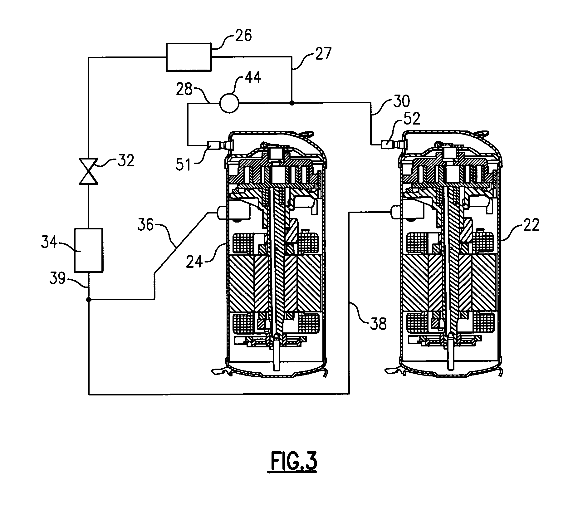
[0011]FIG. 1 shows a prior art refrigerant system 20 incorporating a pair of tandem compressors 22 and 24. As shown, the compressors 22 and 24 are preferably scroll compressors.

[0012]The compressors are provided with discharge ports (tubes) 51 and 52 that form a part of respective flow connecting discharge lines 28 and 30 leading to a central connecting discharge line 27 that communicates compressed refrigerant to condenser 26. From the condenser 26, refrigerant passes to an expansion device 32, and to an evaporator 34. From the evaporator 34, the refrigerant returns through common suction line 39 that branches off to individual suction lines 36 and 38 to the interior shell of each compressor.

[0013]As is known, an upper part 41 of the compressor is at a discharge pressure. A check valve 42 is typically placed such as in a separator plate 43 within the scroll compressor.

[0014]In the prior art, a control for the tandem compressors may shutdown one of compressors 22 and 24 when a lower...


PUM


Abstract

A refrigerant cycle is disclosed having a number of compressors operating in tandem and supplying a compressed refrigerant to a refrigerant system. Discharge lines communicate a compressed refrigerant to a central discharge line for receiving flow from all tandem compressors. A control is operational to determine a number of compressors need to be operated or whether some compressors should be shutdown to satisfy load requirements. Shutoff valves are placed on discharge lines outwardly of the shell of the compressors. That can be shutdown during part load operation. These shutoff valves are closed when their associated compressors are stopped to prevent backflow of refrigerant from operating compressors through the shutoff compressor, and into the system suction side. Additionally, high pressure differential across the compressor internal discharge check valve is eliminated and the possibility of compressor flooding through a discharge line is reduced. Thus, compressor / system performance is enhanced and reliability is improved.

Description

BACKGROUND OF THE INVENTION[0001]This application relates to a shutoff valve placed on a connecting discharge line downstream of a compressor operating in a tandem compressor arrangement.[0002]Refrigerant systems typically include a compressor delivering a compressed refrigerant from a compressor discharge port to a condenser, and then passing the refrigerant from the condenser to an expansion device, an evaporator, and then back to the compressor suction port. The load demand on the refrigerant cycle may vary. At times, there may be a need for a higher system cooling capacity and hence higher compressed refrigerant flow, and at other times, a lower cooling capacity and consequently lower refrigerant flow.[0003]To provide continuous efficient supply of the desired amount of compressed refrigerant, some larger refrigerant systems utilize tandem compressors. In such systems, two compressors may simultaneously deliver a compressed refrigerant to a downstream heat exchanger, such as a c...

Claims


Application Information

Patent Timeline
Patent Type & Authority Patents(United States)
IPC IPC(8): F25B1/10F25B41/04
CPCF25B2400/075F25B2500/28F25B2600/2519F25B41/24F25B1/00F04B23/04F25B49/02
Inventor LIFSON, ALEXANDERTARAS, MICHAEL F.
Owner CARRIER CORP
Learn More