
Throw type compact reconnaissance robot

a reconnaissance robot and compact technology, applied in the direction of vehicle position/course/altitude control, process and machine control, instruments, etc., can solve the problems of low mobility of reconnaissance robots, inability to use robots in a timely manner, and worsening situation or damage, so as to achieve the effect of reducing the number of accidents

Inactive Publication Date: 2016-03-08
KOREA ADVANCED INST OF SCI & TECH +1
View PDF26 Cites 2 Cited by
  • Summary
  • Abstract
  • Description
  • Claims
  • Application Information

AI Technical Summary

Benefits of technology

The invention is a small, throw-type robot that can be used for surveillance purposes. It is designed to have a long battery life, be stable when dropped, and have a simple mechanism to adjust the camera's view. The technical effects are improved efficiency and stability for battery life and reliability for dropping environments.

Problems solved by technology

Although war does not necessarily break out, a variety of crimes and terrorism take place around us at unexpected times and in unforeseen places.
Most of the spots where the incidents take place frequently do not permit easy access by soldiers, policemen, or rescuers, so that the situation becomes worse or damage is heightened.
Such reconnaissance robots have low mobility due to a relatively large size.
Furthermore, under conditions where the robots cannot gain access due to a narrow passage or a natural disaster, the robots cannot be used in a timely manner.
However, the robots should be light and compact enough to be thrown, which causes difficulty in spatial arrangement.
Thus, only a compact battery can be mounted, so that the robots are restricted by operational time.
Further, the compact reconnaissance robots secure smooth infiltration due to their low height, but they have difficulty in carrying out reconnaissance at a desired height.
Failure of parts of the reconnaissance robot caused by a drop shock when the robot is thrown becomes an important problem in interfering with the popularization of the throw-type reconnaissance robots.

Method used


Image

  • Throw type compact reconnaissance robot
  • Throw type compact reconnaissance robot
  • Throw type compact reconnaissance robot

Examples


first embodiment

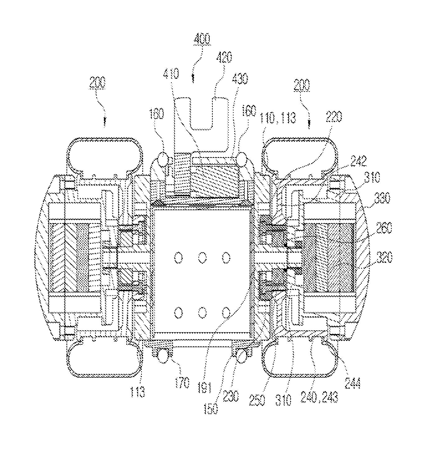
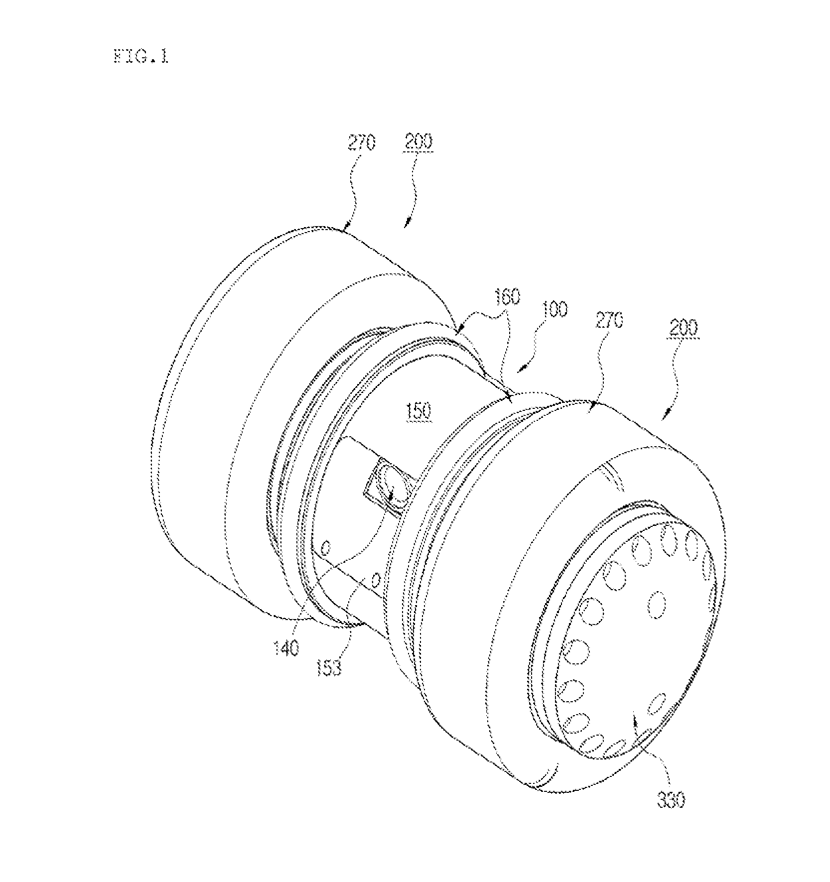
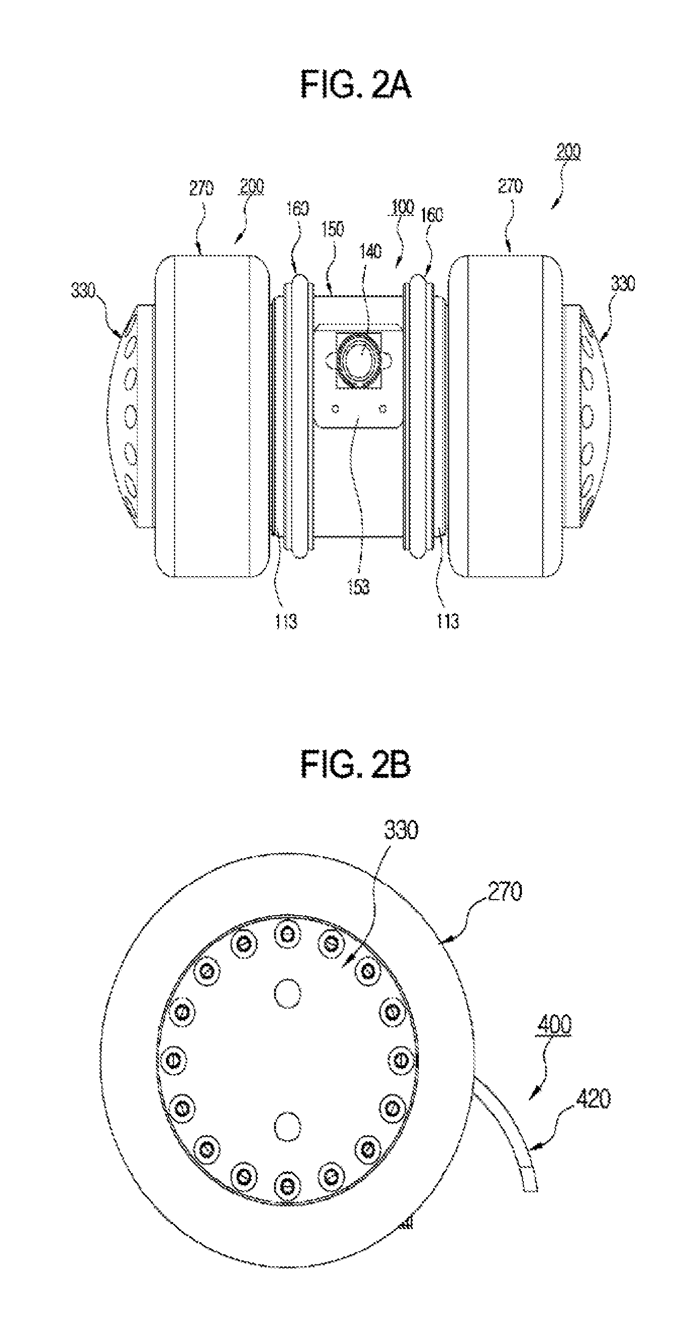
[0037]First, the geometry of the throw-type compact reconnaissance robot 1 according to the present invention will be schematically described with reference to FIGS. 1 and 2A to 2C.

[0038]The throw-type compact reconnaissance robot 1 is generally characterized by a body 100 including a camera 140 and drivers 200 made up of two tires 270 that are disposed on opposite sides of the body 100 and can be driven individually.

[0039]The body 100 is provided with a camera viewing angle adjustor 400 having a tail 420 on the side opposite the camera 140. The camera viewing angle adjustor 400 has a function of adjusting a viewing angle of the camera 140, and a function of ensuring that the entire robot 1 can move relative to the ground by preventing the body 100 from being rotated by a driving force of the tires 270 when the robot 1 moves forward or backward by the drivers 200 having the tires 270.

[0040]Battery units 300, in each of which a battery 320 is mounted, are provided in the axial center...

second embodiment

[0077]Next, a throw-type compact reconnaissance robot according to the present invention will be described in detail with reference to FIG. 8.

[0078]The throw-type compact reconnaissance robot of the present invention may be designed as a reconnaissance robot having four wheels by connecting two modular stand-alone robots 1.

[0079]This connection makes use of a connector member 500 provided specially. To this end, the frame 110 of the body 100 is provided with a fastening area on one side thereof to which the connector member 500 is fastened. Thus, the connection is made by fastening members such as typical bolts. An additional electric part for mounting a high-performance camera may be mounted in an internal connecting space 510 of the connector member 500 which is secured by this connection. Further, this connection makes it possible to drive the robot at a little bit large obstacle terrain and at a rough terrain and to increase the operational time when the battery 320 is additiona...


PUM


Abstract

Provided is a throw-type compact reconnaissance robot, which is used for military purposes or counter-terrorism and is capable of ensuring a long operational time as well as drop safety by efficient spatial layout of a battery. The throw-type compact reconnaissance robot includes a cylindrical body (100) with a camera (140), drivers (200) made up of two tires (270) that are disposed on opposite sides of the body (100) and is drivable individually, and battery units (300) supplying power used to operate the robot and disposed in inner spaces of the tires (270) of the drivers (200) on the opposite outermost sides of the robot.

Description

BACKGROUND OF THE INVENTION[0001]1. Field of the Invention[0002]The present invention relates, in general, to a throw-type compact reconnaissance robot used for military purposes or counter-terrorism and, more particularly, to a throw-type compact reconnaissance robot capable of ensuring a long operational time as well as drop safety by efficient spatial layout of a battery.[0003]2. Description of the Related Art[0004]With the rapid progress of worldwide urbanization, war assumes an aspect of street fighting. Although war does not necessarily break out, a variety of crimes and terrorism take place around us at unexpected times and in unforeseen places. In the event of such incidents occurring, it is essential to grasp the initial situation for rapid and suitable countermeasures. Most of the spots where the incidents take place frequently do not permit easy access by soldiers, policemen, or rescuers, so that the situation becomes worse or damage is heightened.[0005]For this reason, w...

Claims


Application Information

Patent Timeline
Patent Type & Authority Patents(United States)
IPC IPC(8): B62D61/00
CPCG05D1/0038B60K1/04B60K7/0007B60K2001/045B60K2007/0061B60Y2200/24B62D61/00
Inventor KIM, SOOHYUNKIM, KYUNG-SOOKIM, JEEHYOUNGJUNG, WONSUKKIM, CHULYOUNGHONG, YUNSICPARK, HYUNSOOYOO, KYUJELEE, SEOUNG HOLEE, MIN-GUKOH, DOO-YEOLKANG, BONG SOO
Owner KOREA ADVANCED INST OF SCI & TECH
Learn More