Small-size hydraulic buffer for elevator

A hydraulic buffer and hydraulic buffer technology, applied in the field of buffer devices, can solve the problems of unsatisfactory buffer process performance, limited buffer mass range, inability to reduce height, etc., achieving light weight, saving building installation space, and small inertia Effect

Inactive Publication Date: 2007-08-29
SHANGHAI JIAOTONG UNIV
View PDF0 Cites 0 Cited by
  • Summary
  • Abstract
  • Description
  • Claims
  • Application Information

AI Technical Summary

Problems solved by technology

With the existing plunger spring return type hydraulic buffer, the height cannot be reduced, the size can be reduced, the performance of the buffering process is not ideal, and the range of buffering quality is limited, etc.

Method used


Image

  • Small-size hydraulic buffer for elevator
  • Small-size hydraulic buffer for elevator

Examples


Embodiment Construction

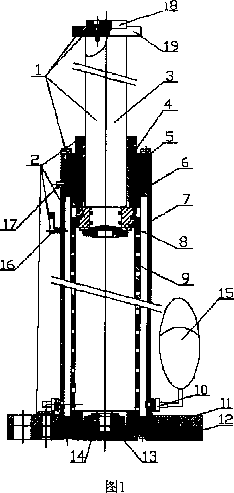
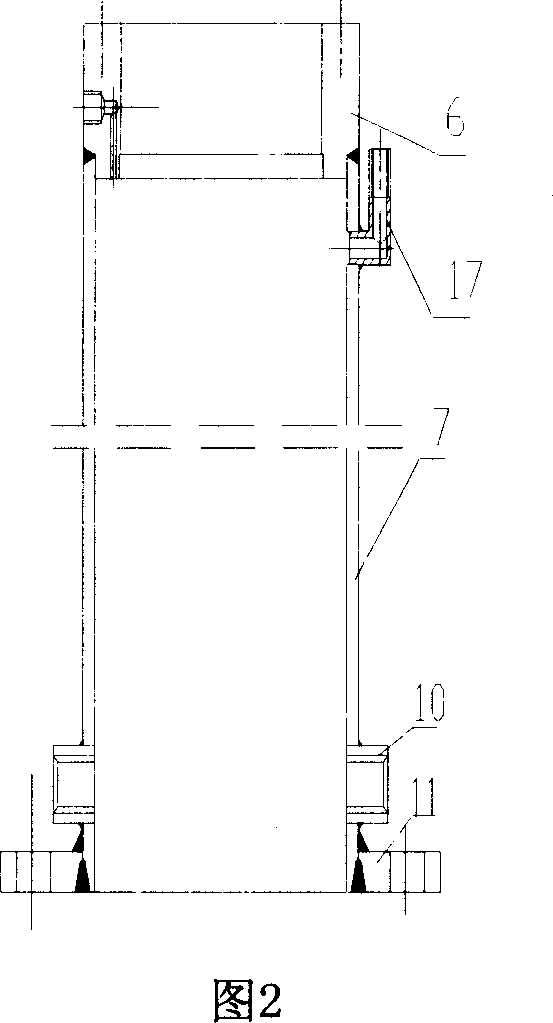
[0016] As shown in Figures 1 and 2, the present invention includes: a piston assembly 1, an outer cylinder body assembly 2, a cylinder head 4, an inner cylinder body 9, a lower base 12, an inner cylinder base 13, a disc spring 14 and an accumulator 15. The connection relationship is as follows: the accumulator 15 is connected with the outer cylinder assembly 2, the inner cylinder 9 is sealed with the piston assembly 1 to form a closed inner cavity through the positioning seal of the inner cylinder base 13 and the fixation of the lower base 12, and the cylinder head 4 Fixed on the outer cylinder body assembly 2, the Belleville spring 14 is fixed on the inner cylinder base 13.

[0017] The outer cylinder assembly 2 is made up of an outer cylinder head 6, an outer cylinder 7, an upper base 11, and a nozzle 16. The outer cylinder 7 is welded on the upper base 11, the outer cylinder head 6 is welded on the outer cylinder 7, and the oil nozzle 16 is welded on the outer cylinder 7 to...


PUM


Abstract

A small-size hydraulic buffer for superhigh-speed elevator is composed of piston module, external cylinder module, cylinder cover, internal cylinder with radial throttle hole, lower base, the base of internal cylinder, butterfly spring and energy accumulator. Its advantages are simple structure, small size, light weight and high buffer effect.

Description

technical field [0001] The invention relates to a buffering device, in particular to a small-sized hydraulic buffer for elevators. Used in the field of mechanical technology. Background technique [0002] At present, the hydraulic buffer mainly realizes two functions of buffering and reset. During the buffering process, throttling is adopted, and springs are used to achieve reset. When a high-speed moving object suddenly hits the buffer, through the action of throttling and spring, the deceleration is controlled, and the moving object is gradually stopped and reset after buffering. According to the European standard EN81-1: 1998 "Safety Regulations for Elevator Manufacturing and Installation", when the car with the rated load falls freely and hits the car buffer at 115% of the rated speed, the average deceleration during the action of the buffer should be No more than 1g; the action time of deceleration above 2.5g should not be more than 0.04s, in order to meet the elevato...

Claims


Application Information

Patent Timeline
Patent Type & Authority Patents(China)
IPC IPC(8): B66B5/28F16F9/084
CPCB66B5/282
Inventor 朱昌明姚荣康詹永麒
Owner SHANGHAI JIAOTONG UNIV
Why Eureka
Try Eureka