
Developing device

A developing device and developer technology, which is applied in electrography, optics, instruments, etc., can solve problems such as increased developer dose, inability to maintain high image quality, and developer deterioration

Inactive Publication Date: 2007-08-29
CANON KK
View PDF8 Cites 0 Cited by
  • Summary
  • Abstract
  • Description
  • Claims
  • Application Information

AI Technical Summary

Problems solved by technology

[0003] Compared with other existing developing methods, the two-component developing method has the advantages of stable image quality and durable equipment. On the other hand, due to long-term use, it is inevitable that the developer, especially the carrier, will deteriorate. phenomenon, therefore, as the image forming device is used for a longer period of time, it is necessary to perform an operation called developer replacement
[0010] However, as described above, if the developer surface is unstable due to the change in bulk density of the developer, the developer cannot be properly discharged, and the balance between the amount of replenished developer and the amount of developer to be discharged deteriorates, and the amount of developer in the developing device gradually decreases. increase, the developer surface rises
[0011] Therefore, when the developer is discharged from the developer discharge port, when the surface of the developer other than the discharge port becomes too high, etc., sometimes poor agitation of the supplementary toner occurs, or due to the above-mentioned change in the bulk density of the developer, if If the amount of developer is increased too much, it becomes a problem of excessive torque and cannot maintain high image quality

Method used


Image

  • Developing device
  • Developing device
  • Developing device

Examples


Embodiment 1

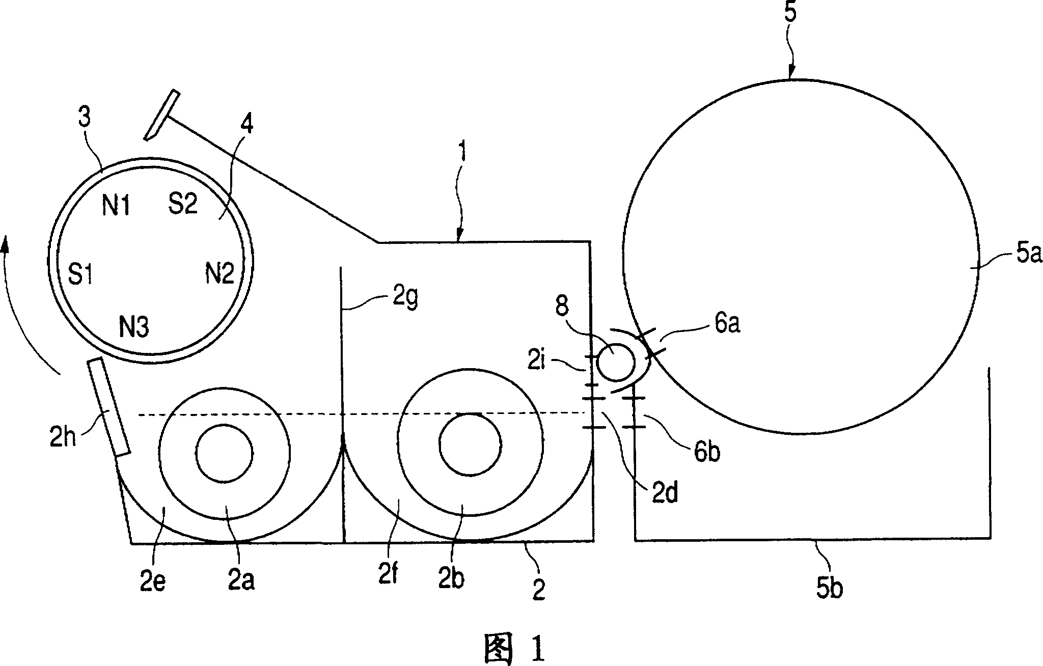
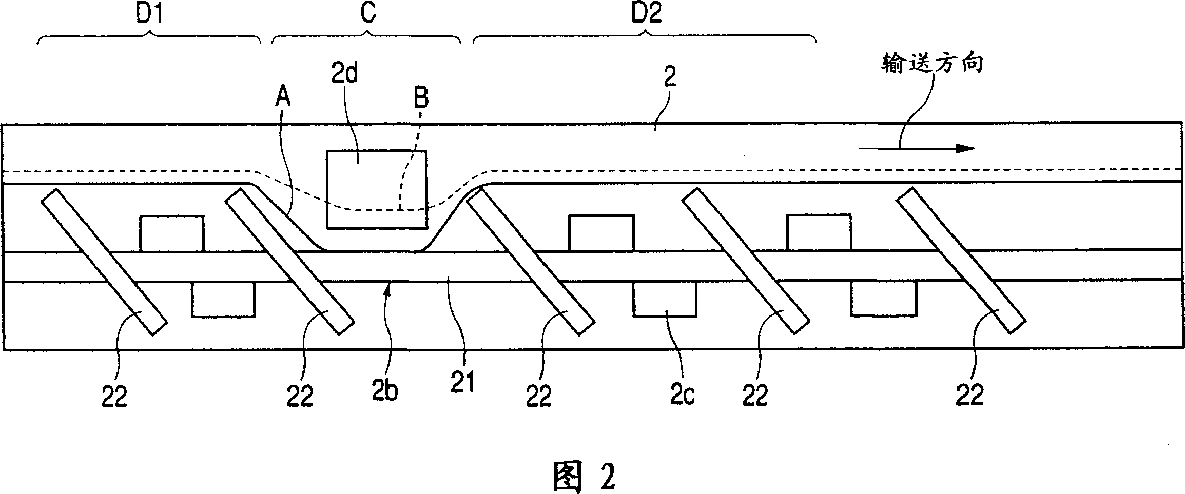
[0024] FIG. 1 is a diagram for explaining a developing device of this embodiment, and FIG. 5 is a diagram for explaining an example of an image forming device using the developing device.

[0025] First, the operation of the entire imaging device will be described. The image forming apparatus of this embodiment has a drum-shaped electrophotographic photoreceptor (photosensitive drum) 128 as an image carrier. In FIG. The exposure forms an electrostatic image on the photosensitive drum 128 , and by developing the latent image with the developing device 1 , a developer image (toner image) is formed on the photosensitive drum 128 .

[0026] After this toner image is transferred onto the recording paper 127 conveyed by the transfer belt 124 by the transfer bias formed by the transfer charger 123, the recording paper 127 is peeled off from the transfer belt 124, The device 125 is pressurized / heated to obtain a permanent image. Also, after the transfer, the residual toner remaining...

Embodiment 2

[0065] Next, a developing cartridge, a second embodiment of the present invention, will be described with reference to FIG. 4 .

[0066] As shown in Figure 4, the developing cartridge 9 of the present embodiment makes the developing device 1 and the developer cartridge 5 in Embodiment 1 integrally made and can be easily installed on or from the imaging device body. disassembled.

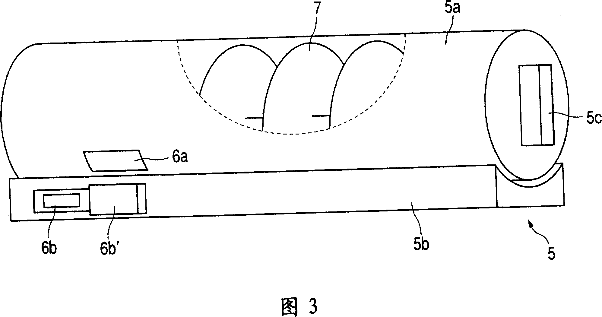
[0067] As in the first embodiment, the supplementary developer container 5 a is fixed so as not to rotate. In addition, the developer replenishment port 6a and the developer recovery port 6b are sealed by the sealing member 6c in the state before being installed in the image forming apparatus. The end portion of the sealing member 6c protrudes a part from the front side of the developing cartridge 9, and after the developing cartridge 9 is inserted into the image forming apparatus body from the front, the developer replenishment port 6a and the developer replenishing port 6a are opened by pulling th...

Embodiment 3

[0070] Hereinafter, an image forming apparatus in which a plurality of developing devices 1 according to Embodiment 1 are arranged inside a rotating body (developing wheel) according to Embodiment 3 of the present invention, and the image forming apparatus which rotates and switches the developing method will be described below with reference to FIG. 6 .

[0071] The electrophotographic image forming apparatus of this embodiment is equipped with an electrophotographic photoreceptor, a photoreceptor drum, which can rotate at a predetermined linear speed in the direction of the arrow in FIG. 128.

[0072] Also, in this embodiment, a photosensitive layer made of an organic photosensitive material is formed on an aluminum cylinder having an outer diameter of 50 mm, and a surface for further improving the release performance of the toner and preventing abrasion of the photosensitive layer is provided. The protective layer.

[0073] The photosensitive drum 128 is charged with electri...


PUM


Abstract

A developing apparatus having a developing container for containing developer including toner and carrier, and developing an electrostatic image formed on an image bearing member, a carrying member for carrying the developer in the developing container, and a discharge port provided in the developing container for discharging any excess developer resulting from the supply of the developer, wherein the developer carrying capability of the carrying member is greater in an area near the discharge port than in an area downstream of the discharge port in the carrying direction of the developer.

Description

technical field [0001] The present invention relates to a developing device for developing an electrostatic image formed by electrophotography or electrostatic recording, and more particularly to a developing device used in copiers, printers, facsimile machines and the like. Background technique [0002] Conventional image forming apparatuses, especially electrophotographic image forming apparatuses that perform color imaging, widely use a two-component development method using a mixture of a non-magnetic toner and a magnetic carrier as a developer. [0003] Compared with other existing developing methods, the two-component developing method has the advantages of stable image quality and durable equipment. On the other hand, due to long-term use, it is inevitable that the developer, especially the carrier, will deteriorate. phenomenon, therefore, as the image forming apparatus is used longer, an operation called developer replacement must be performed. [0004] On the other...

Claims


Application Information

Patent Timeline
Patent Type & Authority Patents(China)
IPC IPC(8): G03G15/06G03G15/00G03G15/08G03G21/00
CPCG03G15/0839G03G15/0872G03G15/0877G03G15/0886G03G15/0893
Inventor 桝田恒司
Owner CANON KK
Learn More