Electromotor of possessing structure for rotational balancing rotor

A rotational balance and motor technology, applied in the field of motors, can solve problems such as affecting the rotational efficiency of the inner rotor and interfering with the alternating excitation efficiency of the outer stator group, and achieve the effects of improving rotational stability, maintaining rotational balance and prolonging service life.

Active Publication Date: 2007-09-05
SUNONWEALTH ELECTRIC MACHINE IND
View PDF2 Cites 0 Cited by
  • Summary
  • Abstract
  • Description
  • Claims
  • Application Information

AI Technical Summary

Problems solved by technology

However, regardless of the permanent magnet ring or the balance piece installed at the bottom of the inner rotor, since the permanent magnet ring or balance piece is located in the center hole of the outer stator group, it will still interfere with the alternating excitation efficiency of the outer stator group, thus affecting the inner rotor. The rotational efficiency of the rotor

Method used


Image

  • Electromotor of possessing structure for rotational balancing rotor
  • Electromotor of possessing structure for rotational balancing rotor
  • Electromotor of possessing structure for rotational balancing rotor

Examples


Embodiment Construction

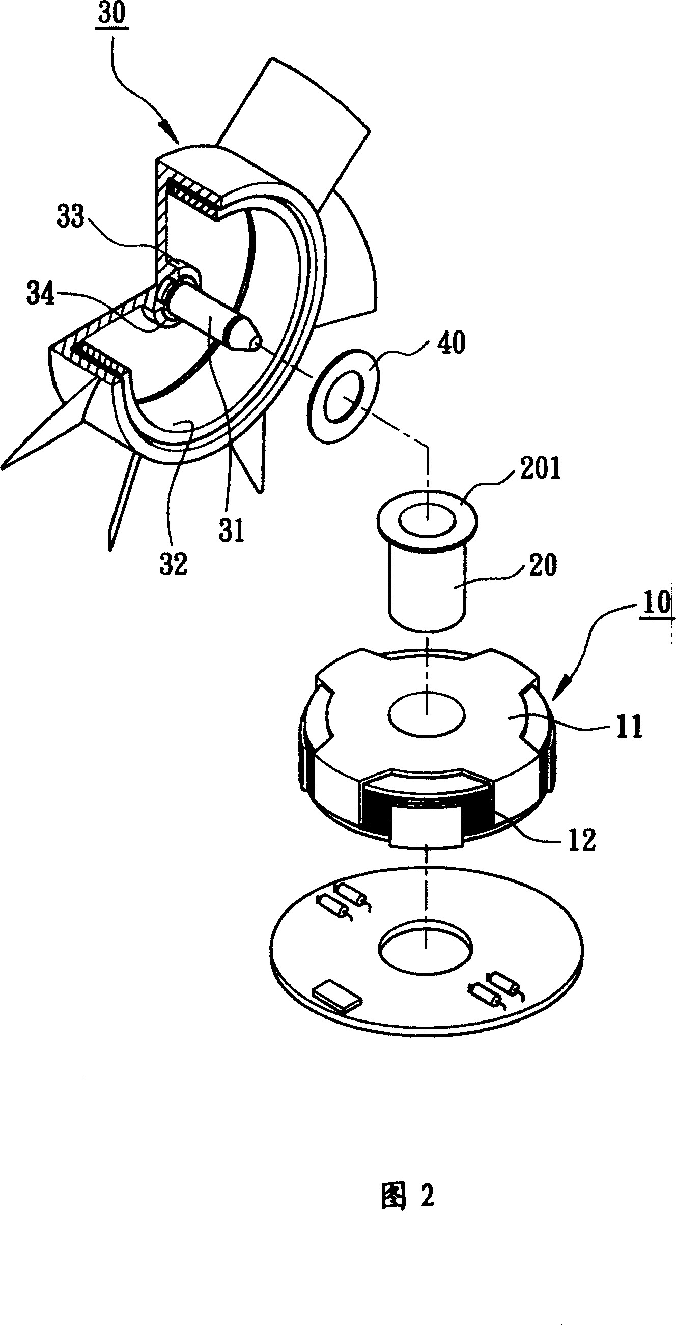
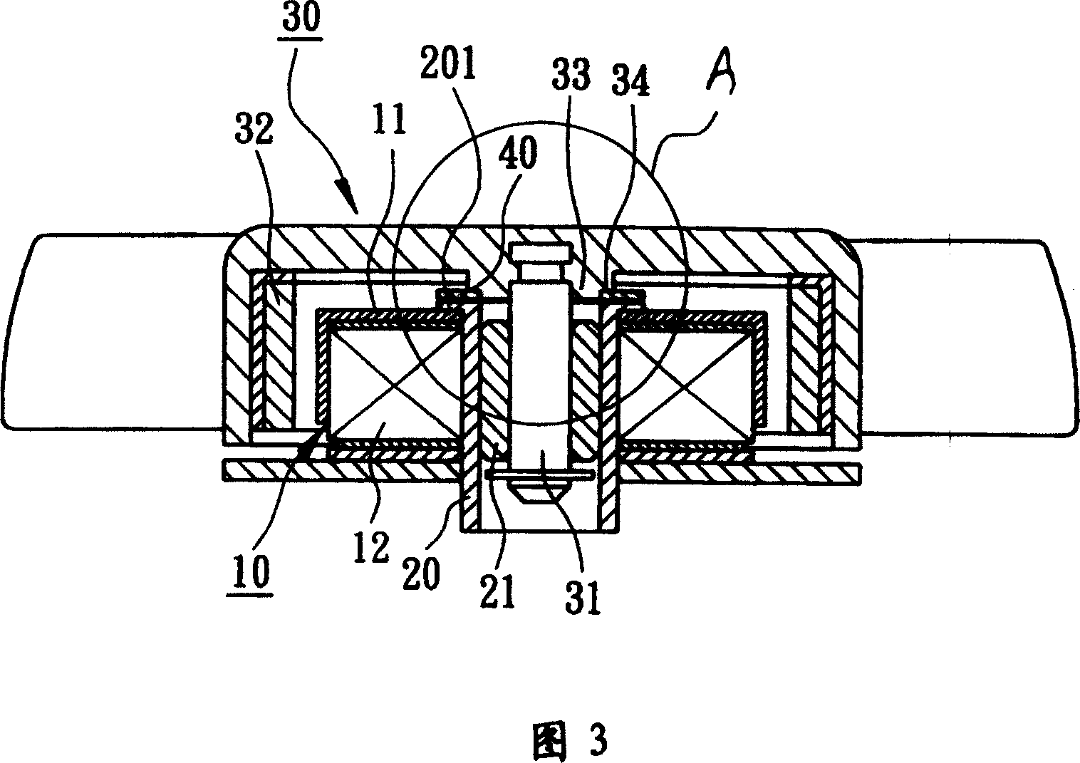
[0036] As shown in FIG. 2 , FIG. 3 and FIG. 4 , the present invention includes a stator 10 , a magnetic sensing part 201 , a rotor 30 and a balance magnet 40 .

[0037] The stator 10 is provided with at least one pole piece 11 , at least one coil 12 that induces the pole piece 11 to generate alternating excitation when alternately energized, and a shaft tube 20 passing through the center axis hole of the stator 10 . The shaft tube 20 is made of a magnetically sensitive material, and a radial flange is disposed on the top of the shaft tube 20 to form the magnetically sensitive portion 201 . The shaft tube 20 fastens and fixes the stator 10 by means of radial flanges, so as to facilitate fixing the stator 10 in a proper position, such as in a housing of a cooling fan.

[0038] The rotor 30 is provided with a shaft 31 , a ring magnet 32 ​​and a shaft seat 33 . The shaft seat 33 protrudes from the center of the lower surface of the rotor 30 , and the shaft seat 33 can form a shou...


PUM


Abstract

The disclosed electromotor possesses advantages of balanceable rotation of rotor, raised rotational stability and prolonged service life. The motor includes stator, induced magnetism part, rotor and balanceable magnet. The stator includes at least a pole piece and a winding as well as an axle tube possessing a top part setup at center of the stator. The rotor includes following parts: shaft seat located at center of lower surface, axial rod extended from the said shaft seat, and ring shaped magnet surrounding pole face of pole piece of stator; induced magnetism part of possessing at least an upper surface formed on top part of the axle tube of stator; fixed on shaft seat of rotor, balanceable magnet possessing a lower face corresponding to upper face of the induced magnetism part.

Description

technical field [0001] The invention belongs to electric motors, in particular to an electric motor with a rotor rotation balance structure. Background technique [0002] As shown in Fig. 1, the announcement number is No. 383818 and the name is "radiator fan group structure with magnetic positioning", which includes a stator 10', a shaft tube 20', a rotor 30' and a magnetically sensitive metal sheet 301'. [0003] The stator 10' is fixed on the base 100' by the shaft tube 20', and the stator 10' is provided with several pole pieces 11'. [0004] The shaft tube 20' accommodates at least one bearing 21'. [0005] The rotor 30' is provided with a shaft 31' and a ring magnet 32'. [0006] The shaft 31' is inserted in the bearing 21', and the ring magnet 32' of the rotor 30' surrounds the pole face corresponding to the pole piece 11' of the stator 10'. [0007] The magnetically sensitive metal sheet 301' is located on the inner surface of the rotor 30' and corresponds to the t...

Claims


Application Information

Patent Timeline
Patent Type & Authority Patents(China)
IPC IPC(8): H02K15/16
Inventor 洪银树洪银农
Owner SUNONWEALTH ELECTRIC MACHINE IND
Why Eureka
Try Eureka