

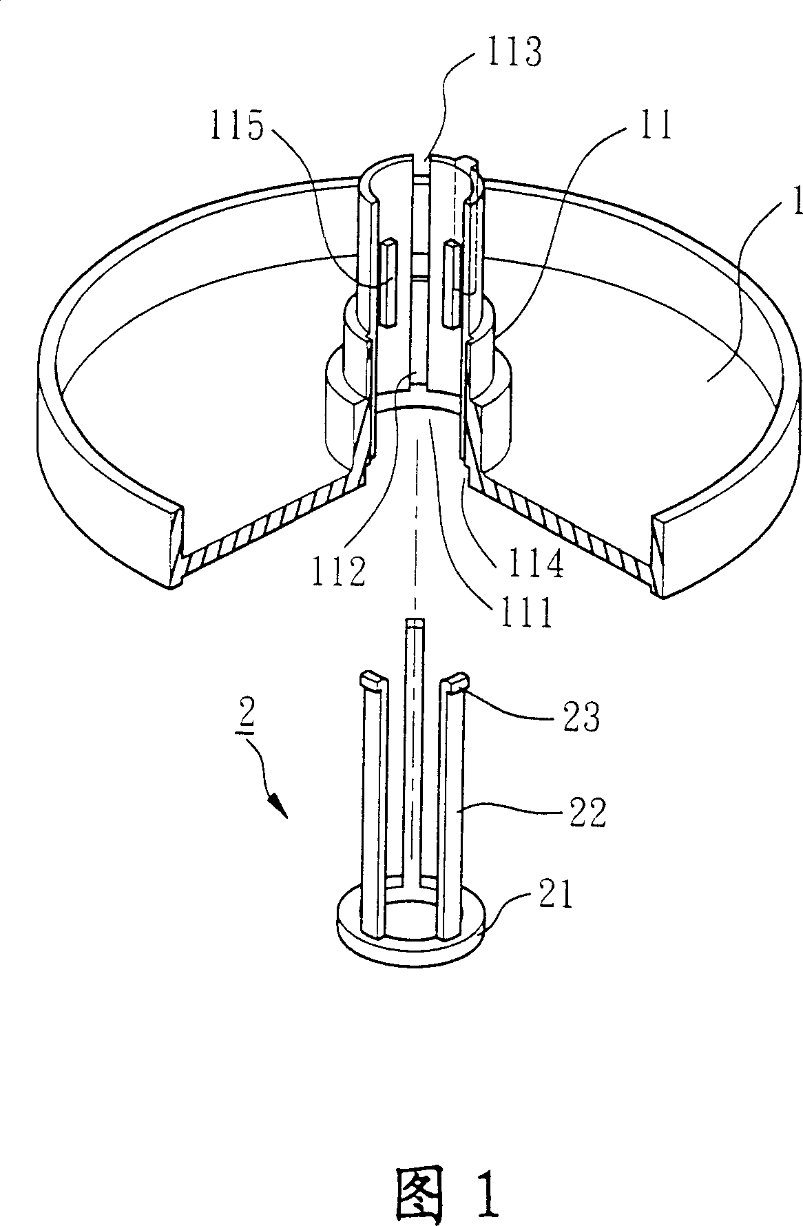
Combined structure of motor axle tube
A motor shaft and structure technology is applied in the field of combined structure of motor shaft tubes, which can solve the problems of low assembly reliability of bearings 4, easy entry of dust, and excessively large gaps of shaft tubes 11.
- Summary
- Abstract
- Description
- Claims
- Application Information
AI Technical Summary
Problems solved by technology
Method used
Image

Examples
Embodiment Construction
[0040] In order to make the technical problems, features, and advantages of the present invention more clearly understood, preferred embodiments of the present invention will be exemplified below in detail with accompanying drawings.
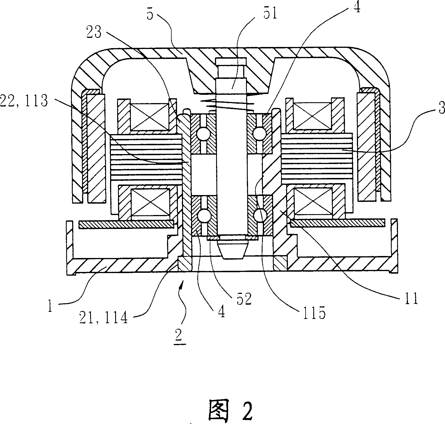
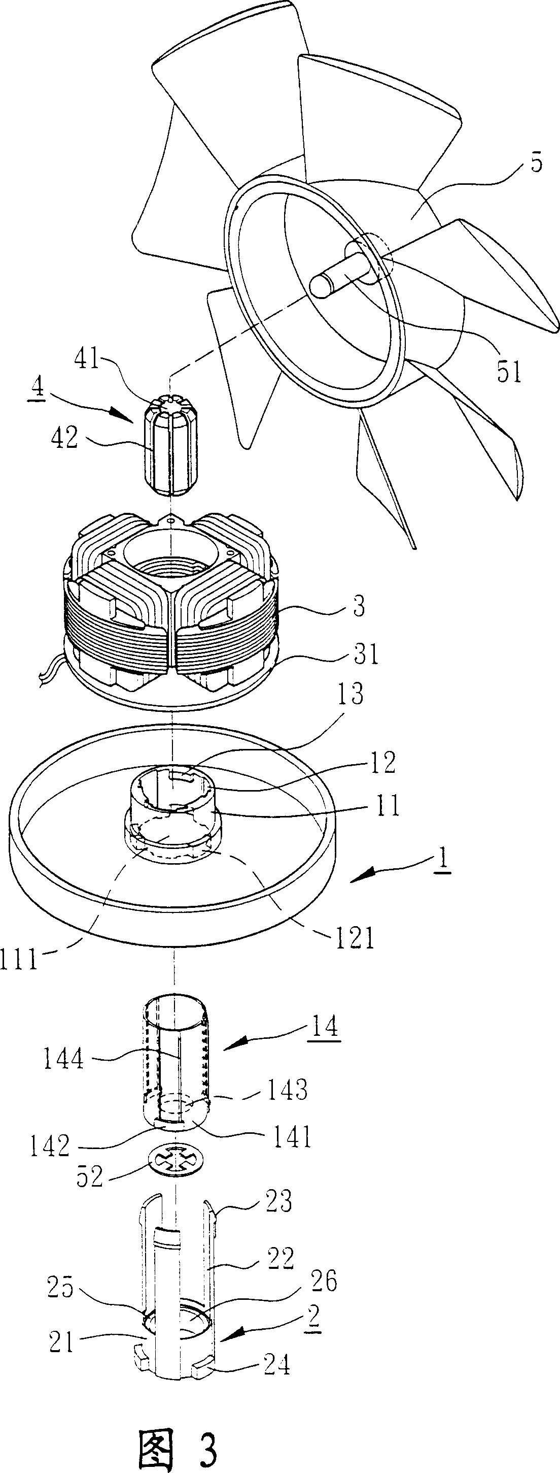
[0041] Fig. 3 discloses an exploded perspective view of the combined structure of the motor shaft tube of the present invention; Fig. 4 reveals a partial sectional view of the combined structure of the motor shaft tube of the present invention; Fig. 5 discloses a partial combined sectional view of the combined structure of the motor shaft tube of the present invention; Fig. 6 reveals A partial combined top view of the combined structure of the motor shaft tube of the present invention; and FIG. 7 shows a combined cross-sectional view of the combined structure of the motor shaft tube of the present invention.
[0042] Some components of the combined structure of the motor shaft tube of the present invention are the same as those of the known combi...
PUM
 Abstract
Description
Claims
Application Information