Combination structure of motor axle tube

A motor shaft and shaft tube technology, which is applied in the field of combined structure of motor shaft tubes, can solve problems such as insufficient assembly reliability, shortened motor service life, and reduced service life, so as to maintain rotor rotation balance and rotation stability, and increase bearing capacity. The effect of improving service life and assembly reliability

Inactive Publication Date: 2007-12-05
SUNONWEALTH ELECTRIC MACHINE IND
View PDF5 Cites 0 Cited by
  • Summary
  • Abstract
  • Description
  • Claims
  • Application Information

AI Technical Summary

Problems solved by technology

[0003] Although the structure of the shaft tube 11 is simple, easy to assemble and can reduce manufacturing costs, the motor only uses the fixing sleeve 11C to maintain the assembly relationship of the bearing 20, the stator assembly 30 and the circuit board 31, which not only has the disadvantage of low assembly reliability , and the shaft tube 11 still has the following other problems in actual use, for example: the bearing 20 is directly combined in the shaft tube 11 without the assistance of a positioning structure, which easily causes the shaft tube 11, the bearing 20 and the rotating shaft 41 The axes of the shafts are inconsistent, thus affecting the rotation stability and generating noise due to rotation imbalance
Furthermore, in the absence of a limiting structure to assist in preventing the fixed sleeve 11C from detaching from the shaft tube 11, when the rotor 40 rotates and causes the axial vibration of the shaft 41, a buckle 20a at the end of the shaft 41 may Axially push the bearing 20 and the fixed sleeve 11C away from the shaft tube 11
In addition, after assembly, there is an excessively large gap between the shaft tube 11 and the rotor 40, which also causes the dust entrained by the airflow to easily enter the bearing 20, thereby affecting the oil lubricity of the bearing 20, and further reducing the performance of the rotor 40. Rotating speed
Therefore, when the motor uses the above-mentioned conventional shaft tube 11 structure, problems such as insufficient assembly reliability, unbalanced rotation, noise generation, and reduced service life may be caused, and even the service life of the motor may be shortened due to accidental loosening of the stator components.

Method used


Image

  • Combination structure of motor axle tube
  • Combination structure of motor axle tube
  • Combination structure of motor axle tube

Examples


Embodiment Construction

[0058] In order to make the above and other objects, features, and advantages of the present invention more clearly understood, the preferred embodiments of the present invention will be specifically cited below, together with the accompanying drawings, for a detailed description:

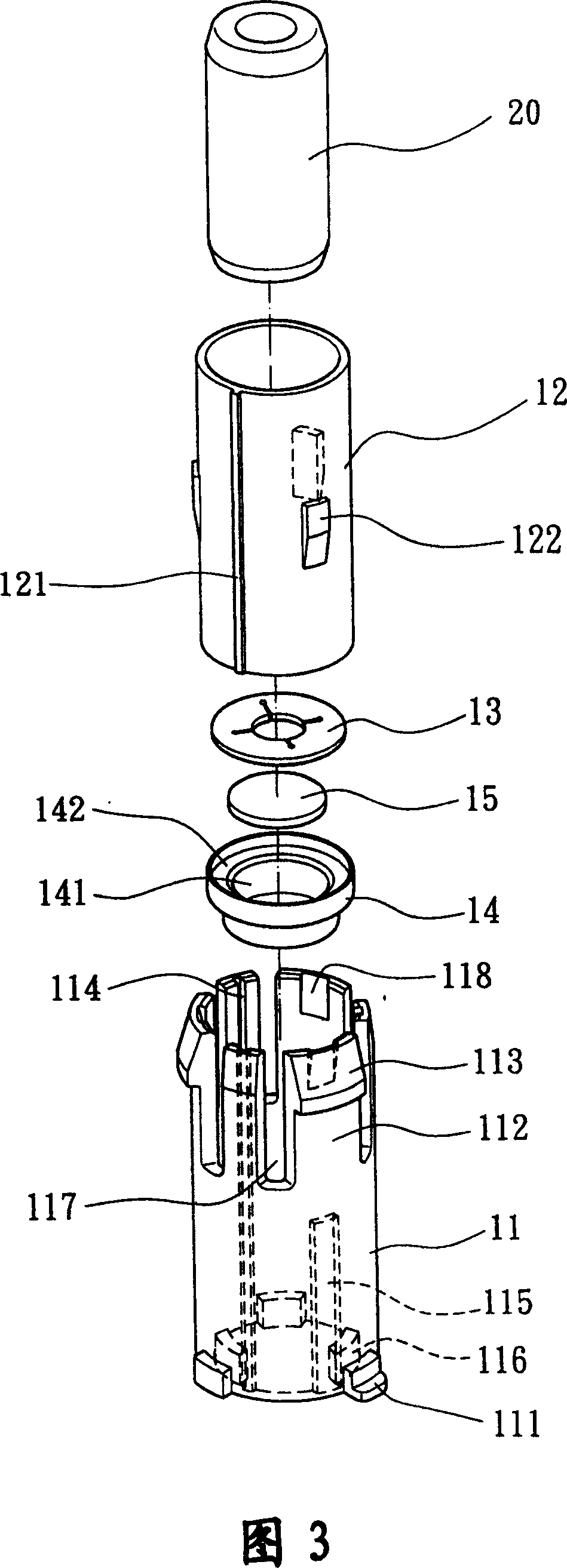
[0059] Fig. 3 discloses an exploded perspective view of the combined structure of the motor shaft tube of the first embodiment of the present invention; Fig. 4 discloses an assembled perspective view of the combined structure of the motor shaft tube of the first embodiment of the present invention; Fig. 5 discloses the present invention along the line 5 of Fig. 4 - Combination sectional view of line 5; FIG. 6 discloses a combined sectional view of the combined structure of the motor shaft tube of the first embodiment of the present invention; FIG. 7 discloses an exploded perspective view of the combined structure of the motor shaft tube of the second embodiment of the present invention; FIG. 8 disclo...


PUM


Abstract

A combination structure of the axle tube of the motor includes one axle tube and one axle box. The axle tube can be fixed on a columella. On the wall of the axle box, there is at least one preliminary detent, whose external diameter can be used to combine one group of stators. The axle box is fixed in the axle tube and can contain an axletree. The axle cover has at least one secondary detent. When assembling, the axletree is set in the axle cover and the secondary detent locks the preliminary detent. Then, the axle tube and the axle box cramp each to combine the stator group and the axletree.

Description

technical field [0001] The present invention relates to a combination structure of a motor shaft tube, in particular to the combination of a shaft tube and a shaft sleeve to improve the assembly reliability of the stator, strengthen the positioning of the bearing, and maintain the rotation balance and rotation stability of the motor rotor sex. Background technique [0002] The shaft tube structure of conventional motors, such as Taiwan Announcement No. 427433 "Fan Bushing Structure Improvement" new patent, please refer to Fig. 1 and Fig. 2 shown, it is to comprise a casing 10, a bearing 20, a stator group 30, A circuit board 31 and a rotor 40 . The center of the shell base 10 is integrally formed with a shaft tube 11 , a stepped portion 11 a is formed on the inner wall of the shaft tube 11 , and several slots 11 b are formed on the top of the shaft tube 11 . The notch 11b makes the shaft tube 11 expandable. Therefore, when the shaft tube 11 accommodates the bearing 20, th...

Claims


Application Information

Patent Timeline
Patent Type & Authority Patents(China)
IPC IPC(8): H02K1/18H02K7/00H02K7/08
Inventor 洪银树洪银农洪庆升
Owner SUNONWEALTH ELECTRIC MACHINE IND
Why Eureka
Try Eureka