Motor structure

A structure and motor technology, applied in the field of motor balance structure, can solve the problems of reducing the actual balance effect of the magnetic induction part, difficult to precisely align and assemble the magnetic induction part, reducing the magnetic attraction balance force, etc., so as to ensure the rotation efficiency and the actual balance. Efficiency, maintaining rotational balance and rotational stability, simplifying the effect of the balance structure process

Inactive Publication Date: 2009-04-22
SUNONWEALTH ELECTRIC MACHINE IND
View PDF6 Cites 0 Cited by
  • Summary
  • Abstract
  • Description
  • Claims
  • Application Information

AI Technical Summary

Problems solved by technology

[0004] Even so, the above-mentioned rotation balance structure generally has the following problems in fact, for example: (1), the size of the metal sheet of the magnetic sensing part usually corresponds to the magnet (such as a ring magnet) of the magnetic attraction part with a maximum area as much as possible, However, this may cause the magnetically sensitive part and the magnetically attracted part to provide an excessively balanced magnetic force.
Furthermore, although the different magnetically sensitive parts of the same plate are adjacent to each other, they are attracted by the N and S pole regions with different polarities on the rotor, which may cause mutual interference between the magnetically sensitive parts, and then relatively reduce the The actual balance effect of the magnetic sensing part (2). In order to overcome the above-mentioned problems, some known rotational balance structures are provided with several magnetic sensing parts in the form of short pieces separately to appropriately reduce the magnetic force of the magnetic balance, so as to avoid excessive influence on the The rotation efficiency of the rotor. However, the technology of separately setting up several magnetic sensing parts has led to the problem that it is not easy to precisely align and assemble each magnetic sensing part

Method used


Image

  • Motor structure
  • Motor structure
  • Motor structure

Examples


Embodiment Construction

[0042] In order to make the above and other objects, features and advantages of the present invention more clearly understood, preferred embodiments of the present invention will be exemplified below and described in detail in conjunction with the accompanying drawings.

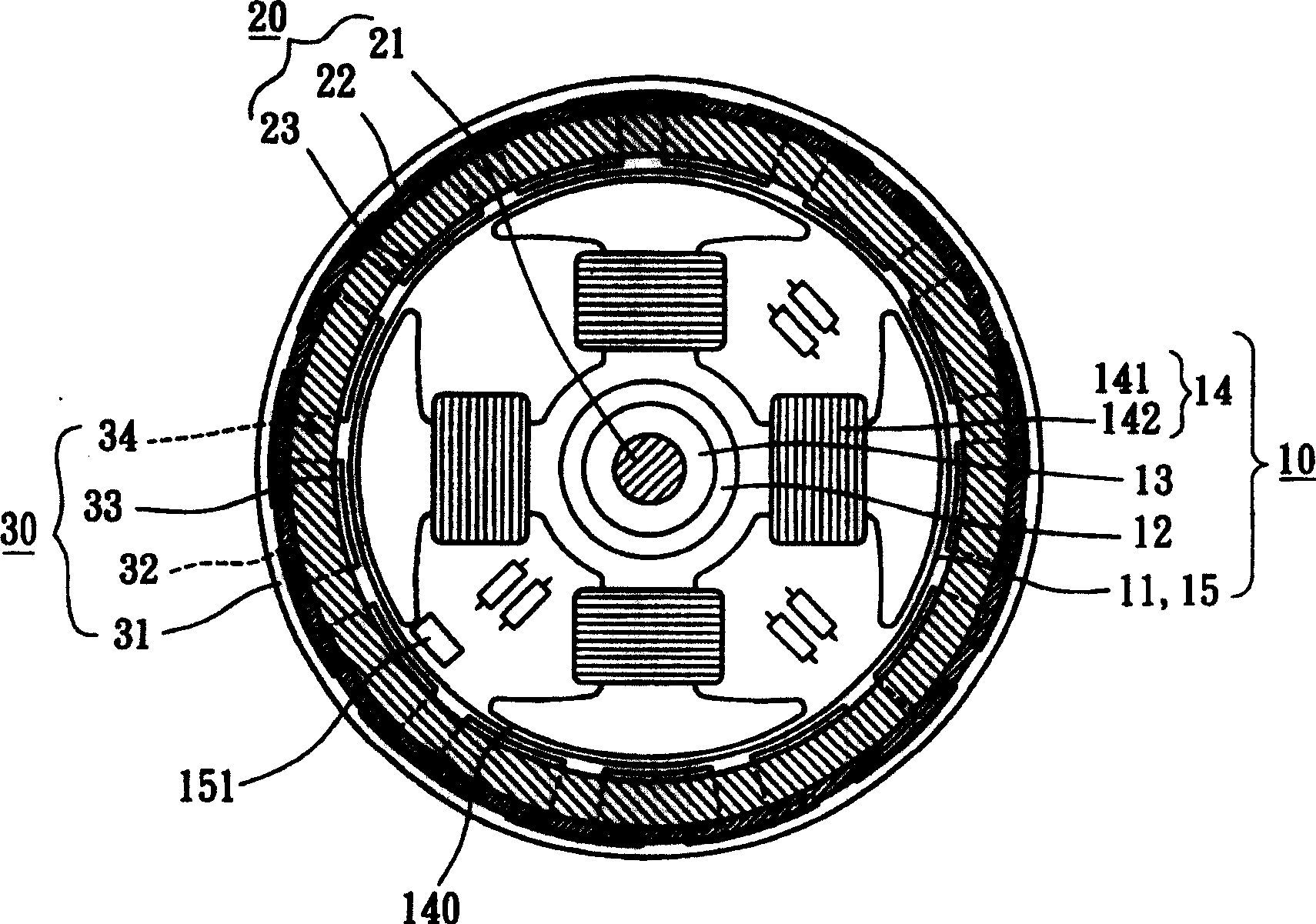
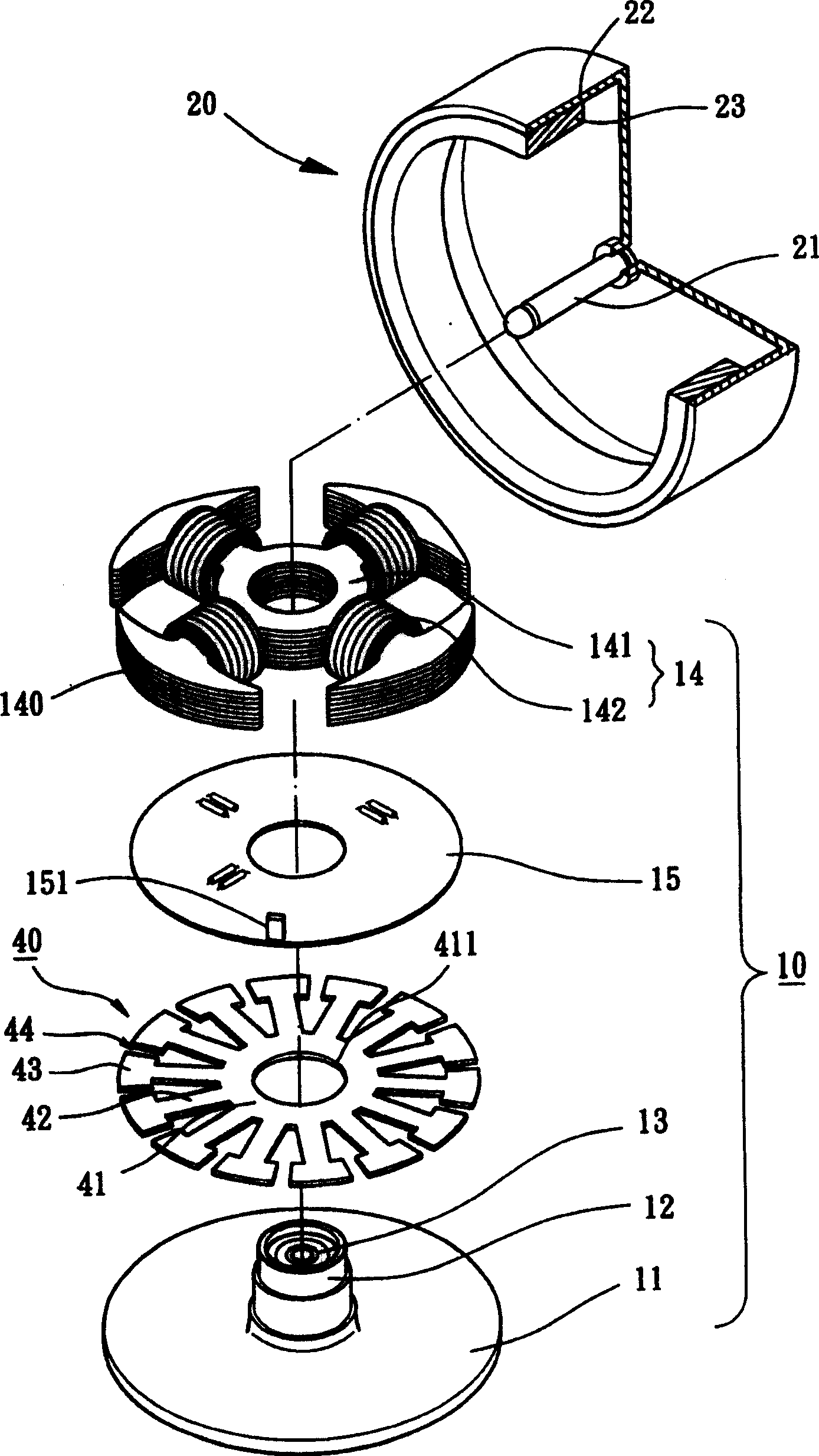
[0043] Please refer to figure 1 As shown, the motor structure of the first embodiment of the present invention includes a fixed part 10, a rotor 20 and a magnetic induction balance piece 30, which can be applied to high-tech motor fields such as cooling fans or optical drive spindle motors, especially small and wireless motors. brushed DC motor field.

[0044] Please refer to figure 1 and figure 2 As shown, the fixing part 10 of the first embodiment of the present invention is provided with a base 11 , a shaft tube 12 , a bearing 13 , a stator assembly 14 and a circuit board 15 . The base 11 is a housing (not shown) that can be combined with a motor. The shaft tube 12 can be selected to be manufactured s...


PUM


Abstract

The invention discloses a motor structure, which comprises the following parts: fixing part, rotor and magnetic induction balance piece, wherein the fixing part contains stator group and at least one induction element; the stator group possesses at least one coil and several magnetic pole planes; the rotor concludes a ring-shaped magnet, which corresponds magnetic pole plane of stator group; the magnetic induction balance piece is set on the fixing part to form integral connecting part and at least two magnetic induction planes, which supports and connects the magnetic induction planes; the magnetic induction plane displays ring-shaped magnet, which provides fitful symmetrical magnetic attraction balance effect. The invention simplifies the manufacturing procedure and reduces manufacturing cost, which guarantees rotary and balancing efficiency.

Description

technical field [0001] The present invention relates to a motor structure, in particular to a fixed part provided with a magnetically sensitive balance piece, which is integrally formed to form a connecting part and at least two magnetically sensitive surfaces for maintaining the balance of rotation, simplifying the structure and facilitating the motor balance of assembly structure. Background technique [0002] Known rotational balance structures of motor rotors, such as China Taiwan Announcement No. 383818 "Radiator Fan Group Structure with Magnetic Positioning", No. 422365 "Radiator Structure with Magnetic Positioning Fan Group", No. 428838 "Motor Rotor Structure" Positioning Structure” and No. 241969 “Fan Motor” and other new patents, and U.S. Patent No. 6,097,120 “Brushless DC Motor Assembly (Brushless D.C. Motor Assembly)”, No. 6,727,626 “Motor Balance Plate Motor), No. 6,483,209 "Balance Rings for Motors", No. 6,700,241 "Positioning device for Prestressing Magnet of ...

Claims


Application Information

Patent Timeline
Patent Type & Authority Patents(China)
IPC IPC(8): H02K1/12H02K1/27H02K29/06H02K7/04H02K3/04
Inventor 洪银树洪银农
Owner SUNONWEALTH ELECTRIC MACHINE IND
Why Eureka
Try Eureka