Motor casing

A technology of outer shell and inner shell, which is applied in the direction of electromechanical devices, electrical components, electric components, etc., can solve problems such as lower production efficiency, loose bolts, and problems, so as to improve production efficiency, maintain stability, and reduce work volume effect

Inactive Publication Date: 2007-09-19
MINEBEA CO LTD
View PDF7 Cites 0 Cited by
  • Summary
  • Abstract
  • Description
  • Claims
  • Application Information

AI Technical Summary

Problems solved by technology

[0004] The above-mentioned motors disclosed in the publications listed above are complex in connection operation, where the connection operation means that the two casing sections are bolted together, while the stator is held between the stator insertions of the two casing sections state, and at the same time such motors tend to increase the number of parts
Also, there is the problem of a large number of manufacturing steps because of the steps required to make the bolt holes and threaded holes for bolting the individual shell segments together
Also, metal particles generated when the unit is fastened by turning the bolts can enter the small air gap between the rotor and the switch, causing problems in turning
These problems tend to reduce production efficiency, so there is a need to develop technologies that can solve these problems
Also, in constructions where the parts are bolted together, there is a risk that the bolts will loosen over long periods of operation, tending to cause rattling sounds and swinging where the stator is held

Method used


Image

  • Motor casing
  • Motor casing
  • Motor casing

Examples


Embodiment Construction

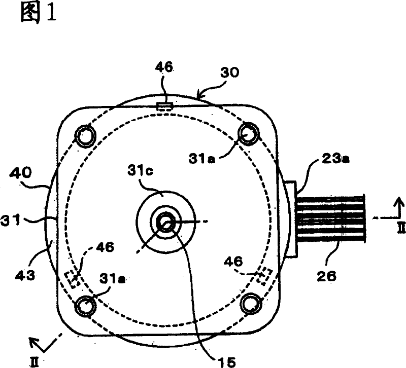
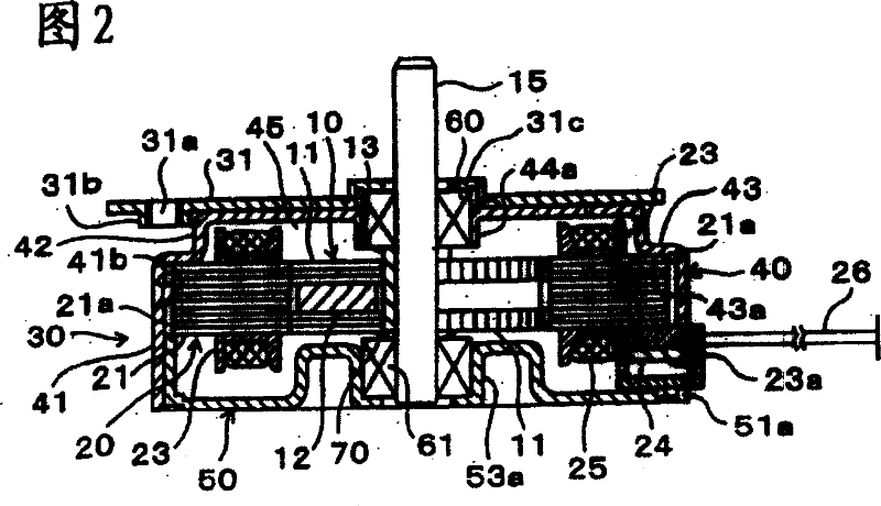
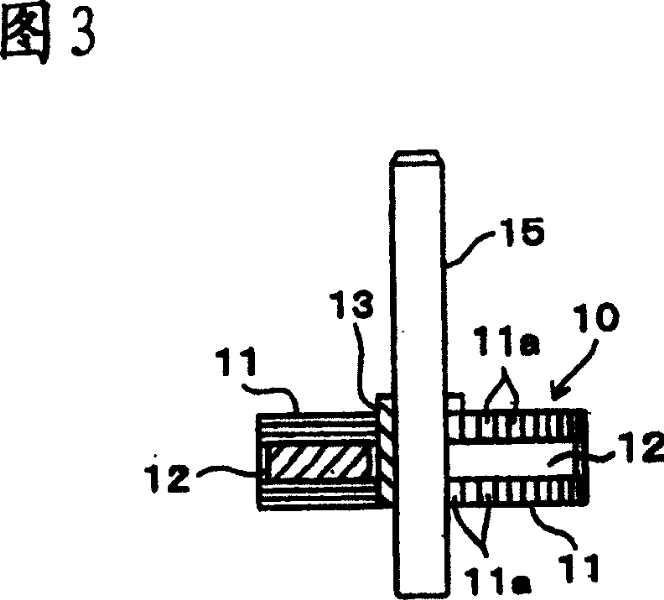
[0027] Embodiments of the present invention applied to a stepping motor will be described below with reference to the drawings. FIG. 1 is a top view of a stepping motor according to an embodiment of the present invention. FIG. 2 is a cross-sectional view along section II-II from FIG. 1 . In FIG. 2 , 10 is a rotor, 20 is a stator disposed around the rotor 10 , and 30 is a casing covering the rotor 10 and the stator 20 .

[0028] As shown in FIG. 2, the housing 30 is composed of a cylindrical outer housing (hereinafter referred to as the front housing) 40 and an inner housing (hereinafter referred to as the rear housing) mounted on the opening side of the front housing 40 at the bottom center of the figure. Body) 50 combined composition. , as can be seen in FIG. 1, a square front plate (joint portion) 31 is fixed to the top surface of the front case 40 by, for example, welding. For example, a through hole is formed by drilling processing at the corner of the front plate 31, a...


PUM


Abstract

A rear casing (inner casing) 50 that fits into a front casing (outer casing) 40, where a stator 20 is held between these casings 40 and 50. The front casing 40 and the casing [SIC] 50 are rigidly adhered to each other through caulking, adhesives, or welding. Furthermore, the elastic parts 46 that provide an elastic force on the stator 20 towards the rear casing 50 at the step part 43 of the front casing 40, where the stator 20 is press fitted, and the restorative force of the elastic pieces 46 strongly holds the stator 20.

Description

technical field [0001] The present invention relates to motors, such as stepper motors, and structures for fastening a stator to a housing. Background technique [0002] Hybrid stepper motors, for example, are often constructed in such a way that a stator with coils wound around an annular stator lamination is located in a small air gap around a rotor with magnets attached to the rotor lamination, which is made of thin Laminations pressed by iron plates, similarly, rotor laminations are also laminations pressed by thin iron plates. In this type of stepper motor, when current is supplied to the coils, the poles of the rotor are connected to the poles of the stator, causing the rotor to remain in a specific position, where by changing the phase of the current supplied to the coils, the rotor gradually rotate. [0003] Generally, motors, including the above-mentioned stepping motors, have a protective case that accommodates a rotor and a stator, wherein a shaft serving as an ...

Claims


Application Information

Patent Timeline
Patent Type & Authority Patents(China)
IPC IPC(8): H02K5/02H02K37/00H02K1/18H02K5/00H02K5/04H02K5/16H02K37/04
CPCH02K5/04H02K1/185H02K5/00H02K5/161
Inventor 大利章
Owner MINEBEA CO LTD
Why Eureka
Try Eureka