Heat carrier and method for the production thereof

A technology of heat conduction and flat tubes, applied in the direction of heat exchanger shells, indirect heat exchangers, heat exchanger types, etc., can solve problems such as difficult processing or forming, and achieve the effect of low cost

Inactive Publication Date: 2007-10-10
BEHR GMBH & CO KG
View PDF6 Cites 0 Cited by
  • Summary
  • Abstract
  • Description
  • Claims
  • Application Information

AI Technical Summary

Problems solved by technology

Because the pressure in CO2 air-conditioning systems is significantly higher than that in air-conditioning equipment using R134a refrigerant in the past, one collector pipe has a relatively thick wall, which makes it difficult to machine or form

Method used


Image

  • Heat carrier and method for the production thereof
  • Heat carrier and method for the production thereof
  • Heat carrier and method for the production thereof

Examples


Embodiment Construction

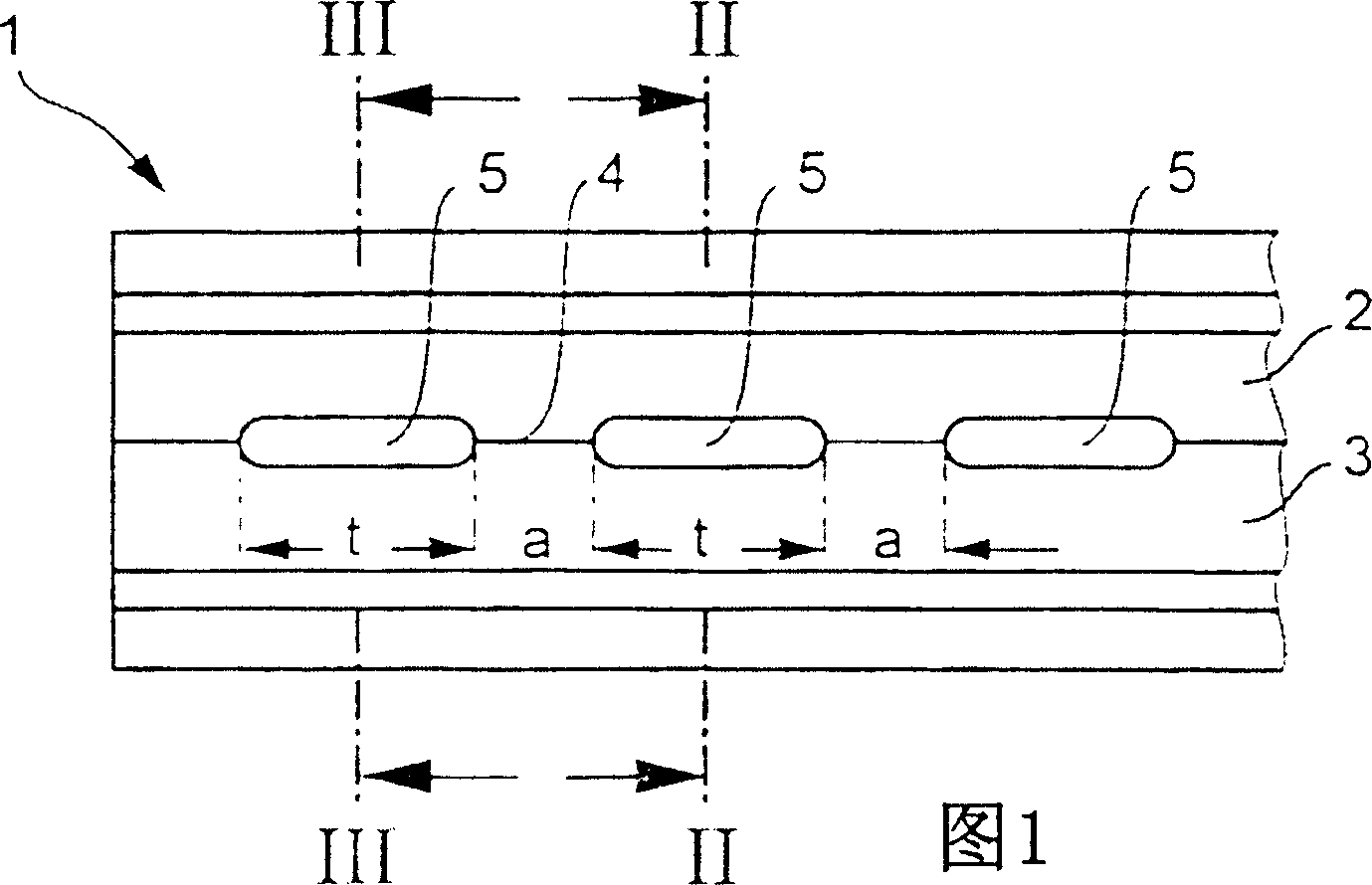
[0018] Fig. 1 is a bottom view of a collector pipe used on a heat exchanger in an automotive CO2-air conditioning system (not shown). The collecting pipe (part) shown in the figure is a notched hollow profile whose edge strips 2 , 3 meet each other at a common seam or parting seam 4 . The seam or parting seam 4 extends in the longitudinal direction, and slot-shaped receiving holes 5 are arranged in this region, the length of which is t, and the distance between the holes is a.

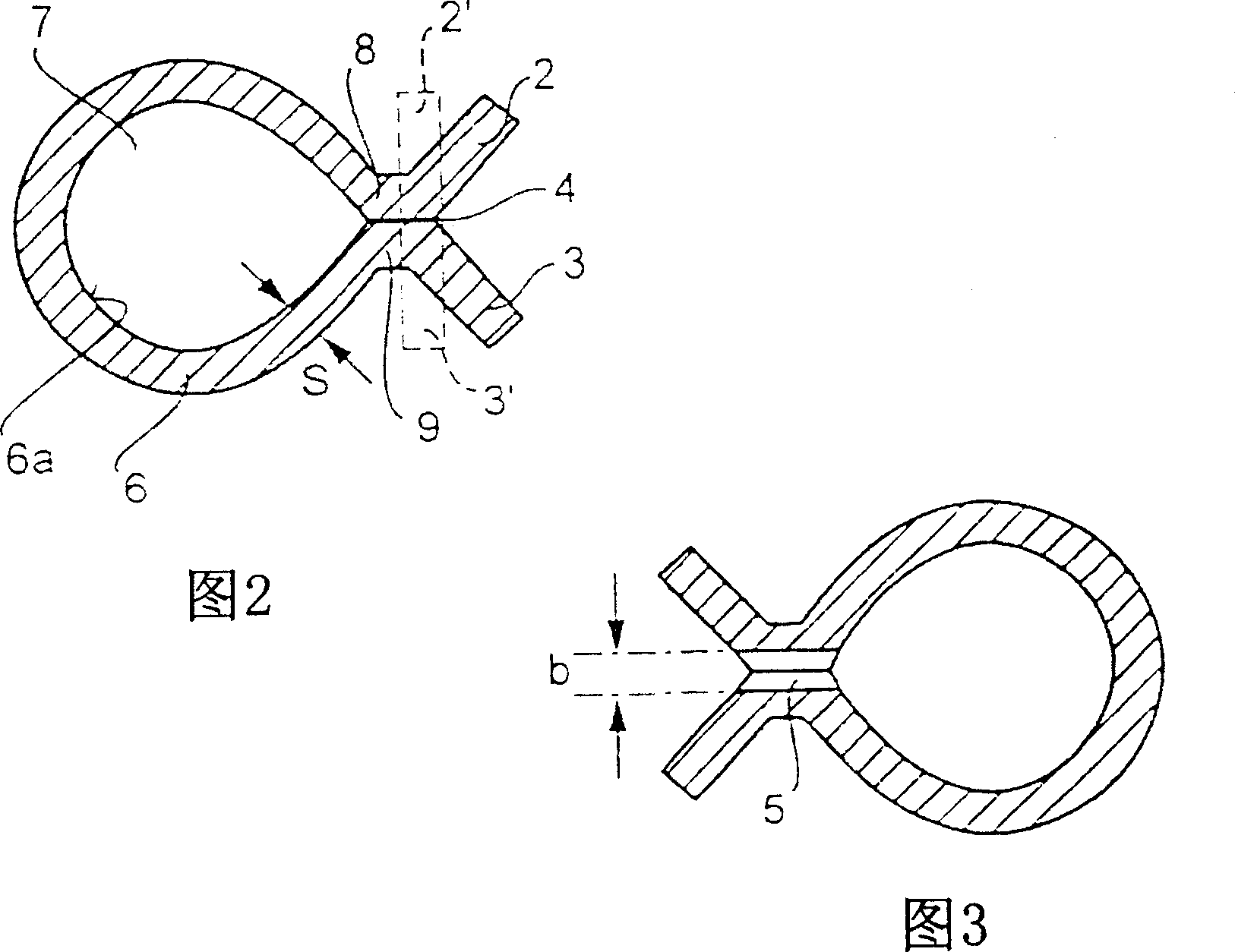
[0019] FIG. 2 shows a section through the collecting pipe 1 , ie along the line II-II in FIG. 1 , that is to say in the region of the seam 4 . The collecting pipe 1 is produced by bending a steel strip 6 of thickness s into a hollow profile 7 , the two projecting sides 8 , 9 of which abut one another and form the joint 4 . The steel strip 6 or the hollow profile 7 continues past the edges 8 , 9 into V-shaped raised edge strips 2 , 3 . Shown in dotted lines are edge strips 2', 3' extending at right an...


PUM


Abstract

The invention relates to a heat carrier comprising at least one collector pipe for receiving the ends of flat pipes, especially for a CO2 air conditioning unit for motor vehicles. The collector pipe is formed by an open hollow profiled section with edges forming a continuous longitudinal slit extending in a longitudinal direction and the ends of the flat pipes, which are twisted at an angle of 90 DEG , are received in a fluidically tight manner in the longitudinal slot. According to the invention, the edges partially abut, forming a separating joint and are partially rolled back, forming receiving openings for the ends of the flat pipes. The receiving openings are produced by plastic deformation.

Description

technical field [0001] The invention relates to a heat conductor with at least one collecting tube for holding flat tube ends according to the preamble of claim 1 of patent DE-A 198 46 267 published by the applicant. Furthermore, the invention relates to a method of manufacturing a heat conductor according to the preamble of claim 7 of the preceding application. Background technique [0002] A heat conductor disclosed by the applicant through DE-A 198 46 267 has a longitudinally extending notch into which the end of the flat tube can be inserted; with respect to the flat tube, the end of the flat tube is twisted by 90° Spend. In this case, the ends of the flat tubes are pressed together, inserted one behind the other into the longitudinal slots and soldered to the collecting tube in a fluid-tight manner. This arrangement makes the distance between the flat tubes arranged in parallel of the heat conductor limited by the depth of the flat tubes (meaning extending in the dire...

Claims


Application Information

Patent Timeline
Patent Type & Authority Patents(China)
IPC IPC(8): F28F9/02F28F9/18F28F1/02F28D1/053B21C37/08B21C37/29B21D22/02B21D53/08B21J5/10F28F9/26
CPCF28D1/05366B21C37/292F28F9/182F28F1/025B21C37/0803F28F9/0243B21J5/10Y10T29/49364
Inventor 瓦尔特·德穆特梅尔廷·科奇卡尔-海因茨·施塔法克里斯托夫·瓦尔特
Owner BEHR GMBH & CO KG
Why Eureka
Try Eureka