Supercharge Your Innovation With Domain-Expert AI Agents!

Car body fore part arrangement

A technology for the front of the car body and the front and rear of the car body, which is applied in the direction of the upper structure, lower structure, vehicle parts, etc., to achieve the effect of improving rigidity and improving absorption performance

Inactive Publication Date: 2007-10-24
HONDA MOTOR CO LTD
View PDF6 Cites 0 Cited by
  • Summary
  • Abstract
  • Description
  • Claims
  • Application Information

AI Technical Summary

Problems solved by technology

[0009] Therefore, the beam 205 is required to be able to absorb the collision energy and driving vibration from the front of the vehicle body. However, there is a limit to how efficiently the beam 205 can absorb the collision energy or driving vibration, so there is room for improvement.

Method used


Image

  • Car body fore part arrangement
  • Car body fore part arrangement
  • Car body fore part arrangement

Examples


Embodiment Construction

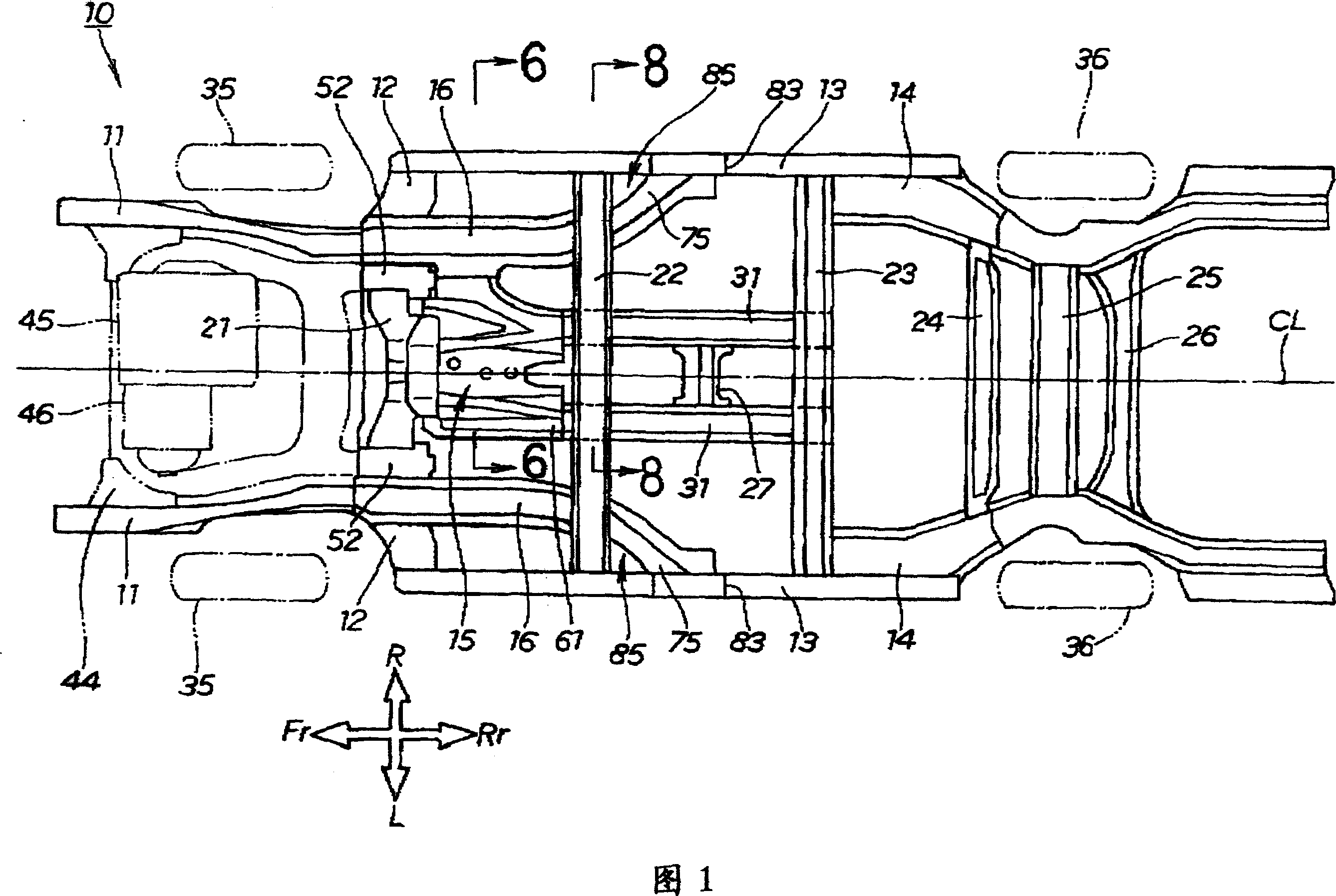
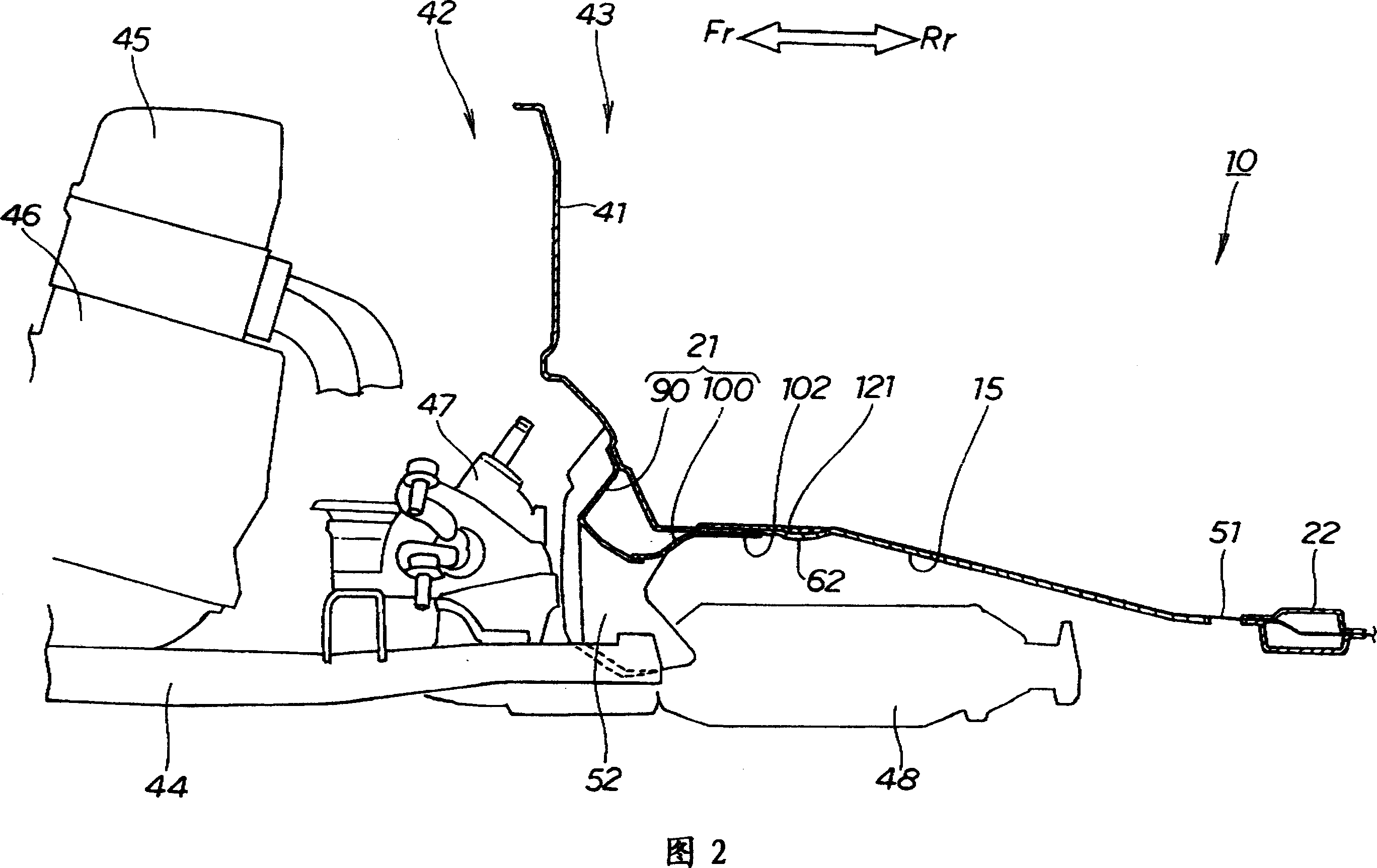
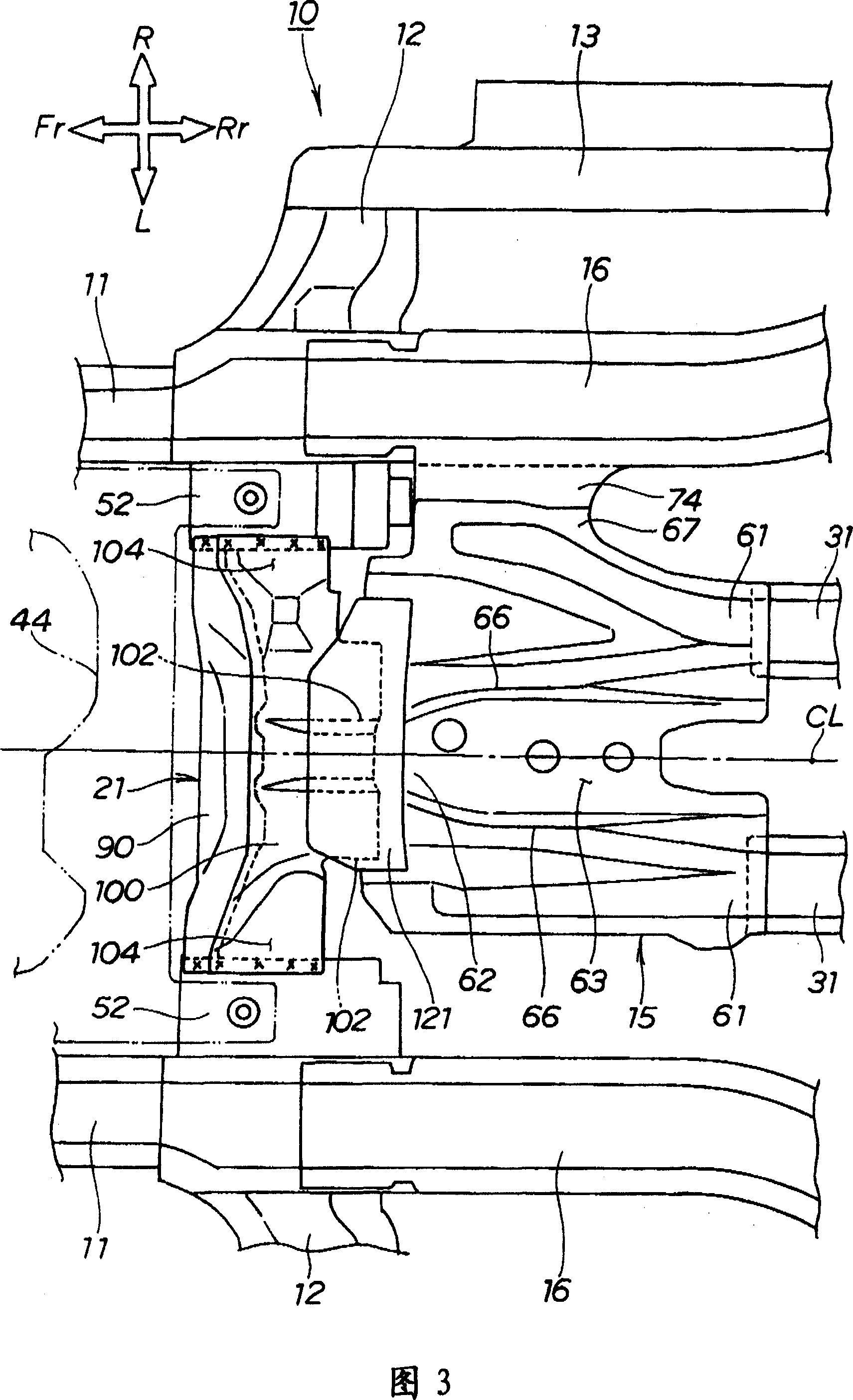
[0038] Hereinafter, the best mode for carrying out the present invention will be described with reference to the drawings. "Front", "Rear", "Left", "Right", "Up", "Down" are the directions seen from the driver, Fr means the front side, Rr means the rear side, L means the left side, and R means the right side side, CL represents the vehicle width center (body center). In addition, the drawing is a figure seen along the direction of a symbol.

[0039] FIG. 1 is a plan view of a vehicle body according to the present invention, showing a vehicle body 10 in a state where a floor is removed. However, for convenience of illustration, only the floor passage 15 is shown.

[0040] The vehicle body 10 of a vehicle such as an automobile is a low-floor vehicle body in which the height of the floor is lowered. The left and right rear side vehicle frames 14, 14, the floor tunnel 15, the floor longitudinal beams 16, 16 and six beams 21-26 extending to the vehicle width direction are used a...


PUM


Abstract

A front part structure of a vehicle body, to efficiently transmit collision energy applied from the front side of a vehicle body to the whole vehicle body from a dash board. The vehicle body 10 has the front part of the vehicle body partitioned by the dash-board 41 into a front part engine room 42 and a rear part cabin 43, wherein a sub-frame 44 for mounting the engine is installed to the right and left front side frames extending in the front and rear direction of the vehicle body within the engine room. A cross member 21 is disposed between the right and left front side frames at the dashboard, and the extension part 102 is extended backward from the cross member, connecting the front end part 62 of a floor tunnel 15 extending in the front and rear directions of the vehicle body to the rear end part of the extension part.

Description

technical field [0001] The present invention relates to a front structure of a vehicle body, in particular to an improvement technique of an instrument panel part. Background technique [0002] In vehicles such as automobiles, a technique of providing a beam on a dashboard portion is known (for example, refer to Patent Document 1). [0003] [Patent Document 1] Japanese Unexamined Patent Publication No. 10-7022 (Fig. 1-Fig. 3) [0004] Patent Document 1 will be described based on the following drawings. [0005] Fig. 19 is a schematic diagram of a conventional vehicle body structure. Fig. 20 is a sectional view taken along line 20-20 of Fig. 19 . [0006] The existing vehicle body 200 divides the front part of the vehicle body into an engine room 202 and a rear vehicle compartment 203 by using a dashboard 201, and forms a channel part 204 of a recessed portion that penetrates front and rear at the central lower part of the instrument panel 201. Immediately above the porti...

Claims


Application Information

Patent Timeline
Patent Type & Authority Patents(China)
IPC IPC(8): B62D25/00B62D21/15B62D25/08B62D25/20
CPCB62D25/2045B62D21/152B62D25/2036B62D25/025B62D25/2018B62D25/082
Inventor 赤坂浩祐
Owner HONDA MOTOR CO LTD
Features
  • R&D
  • Intellectual Property
  • Life Sciences
  • Materials
  • Tech Scout
  • Unparalleled Data Quality
  • Higher Quality Content
  • 60% Fewer Hallucinations
Learn More