Butterfly valve

A technology of rotating baffles and throttle valves, applied in valve devices, lift valves, valve details, etc., can solve the problems of unsealed seals, uneven use of rubber seals, etc., and achieve the effect of simple assembly and material saving

Inactive Publication Date: 2007-10-31
ALFA LAVAL LKM
View PDF10 Cites 2 Cited by
  • Summary
  • Abstract
  • Description
  • Claims
  • Application Information

AI Technical Summary

Problems solved by technology

Variable axial forces transmitted to the rubber seal due to, for example, vibration can adversely lead to uneven utilization of the rubber seal
This may in turn lead to defects that cause the seal to become leaky
[0004] Another disadvantage of the known rotary flapper throttle valve is that due to the use of substantially solid clamping blocks to assemble the valve a considerable amount of material is used

Method used


Image

  • Butterfly valve
  • Butterfly valve
  • Butterfly valve

Examples


Embodiment Construction

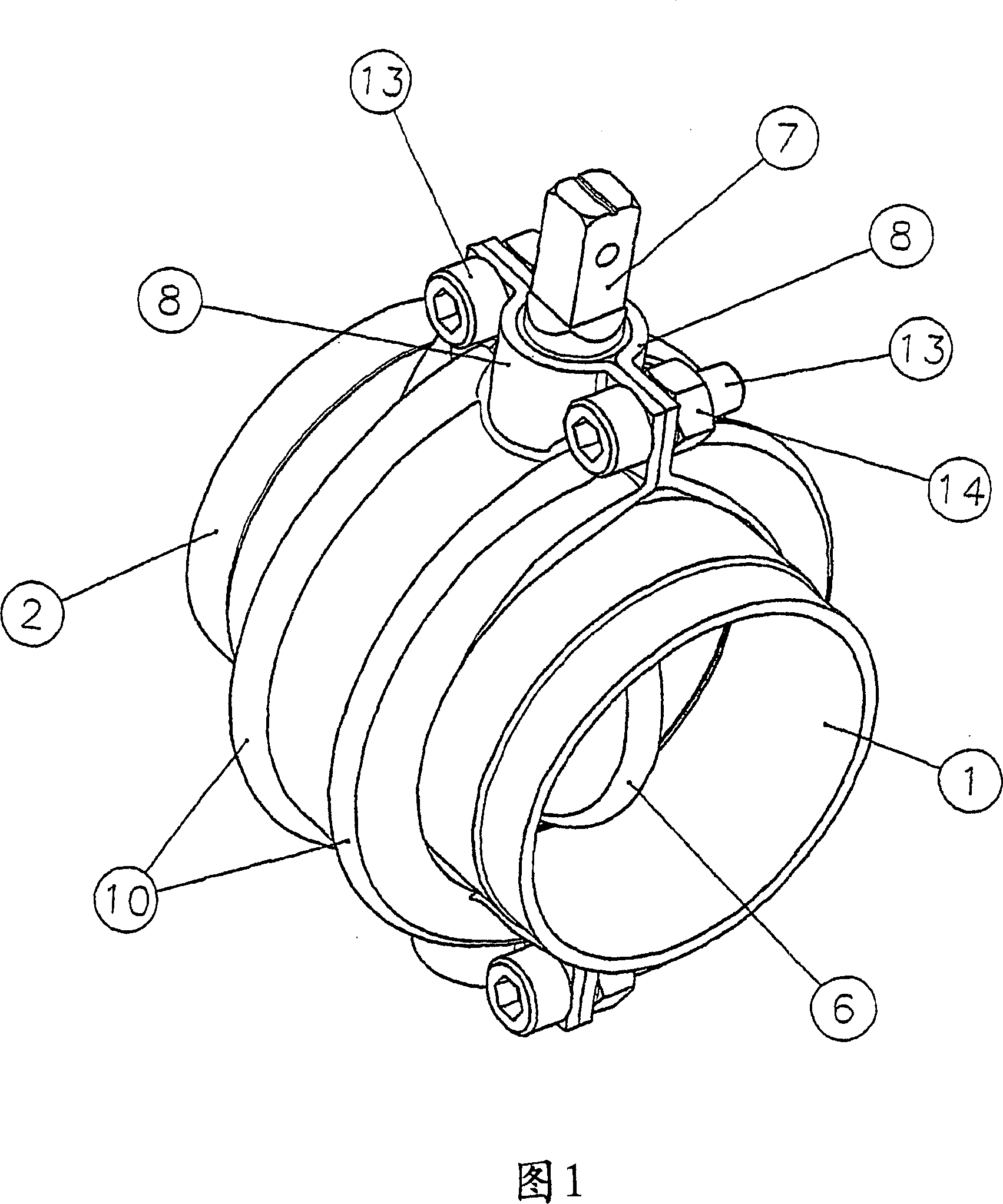
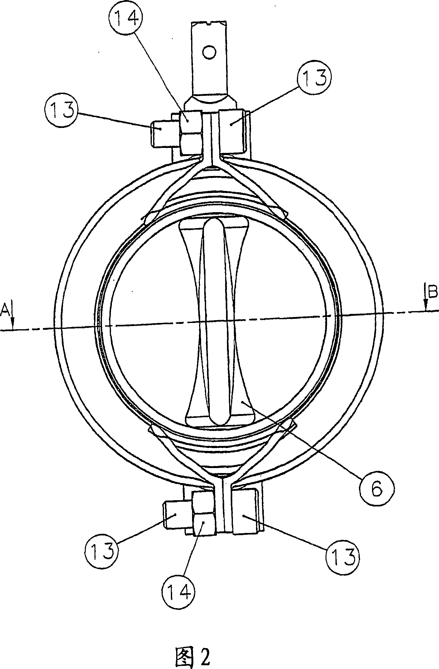
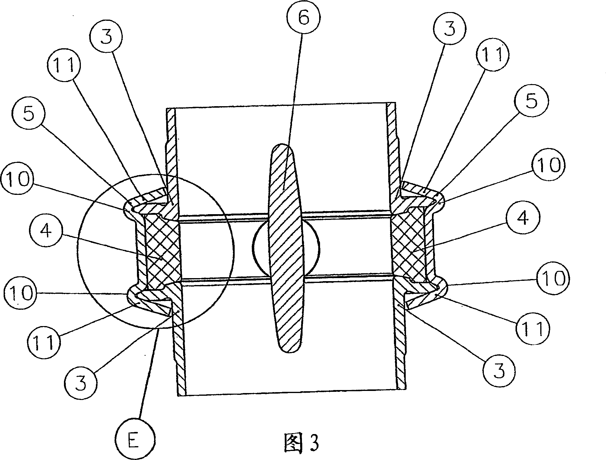
[0025] 1 and 4 show a general view of a rotary flap throttle valve according to the invention, viewed obliquely from above or from the side. As can be seen in the drawing, the valve is formed from a valve inlet part 1 and a valve outlet part 2 . The valve inlet part 1 and the valve outlet part 2 are each provided with a flange 3 , the outer surfaces 15 of which are pressed axially onto the rubber seal 4 via the clamping halves 5 . The rubber seal 4 rests on the valve disk 6 . The valve disk 6 is mounted rotatably via a valve disk rod 7 on a bushing 9 which is inserted into an annular receptacle 8 of the clamping half 5 .

[0026] As can be seen from FIGS. 3 and 1 , the clamping halves 5 are each formed with two annular recesses 10 concentric with the mounting seat of the flange 3 . The recess 10 is beveled at an edge 11 . The flange 3 has a conical taper 12 outwardly. The flange 3 is rigidly connected to the clamping half 5 at its inner and outer contact surfaces 16a and 1...


PUM


Abstract

A butterfly valve includes an annular, elastic sealing element that encloses an axial opening, a valve disk which is disposed inside the axial opening so as to be rotatable transversal to the axial direction, a device for rotating the valve disk between closed and open positions in order to control a fluid flow through the opening, and at least two valve housing parts that enclose the sealing element in an annular manner and embrace two flanges which are connected to an inlet and an outlet. Conical contact areas of the flanges and / or the valve housing parts cooperate in such a way that the flanges are axially pressed in a sealing fashion against the sealing element by means of the valve housing parts in the operationally mounted state. The flanges are respectively connected in a rigid and positive manner to a couple of clamps.

Description

technical field [0001] The invention relates to a rotary baffle throttle valve and an assembly method thereof. Background technique [0002] Such a rotary flap throttle is known, for example, from DE 15 50 499 B2. In the valve proposed there, two flanges connected to an inlet piece and an outlet piece are held together by two clamping pieces. An essentially annular rubber seal, which surrounds a valve disk, is clamped between the flanges. Due to the inclined inner surfaces of the clamping blocks, when the two clamping blocks are radially pressed together, axial forces act on the flanges in addition to radial forces, which cause the flanges to move towards each other. In the ready-to-operate assembled state, the flange end face of the clamping rubber seal is not in contact with the clamping block. The connection of the flange to the clamping block is formed only indirectly via the seal and on the back facing away from the rubber seal. Thus, the connection is elastic axial...

Claims


Application Information

Patent Timeline
Patent Type & Authority Patents(China)
IPC IPC(8): F16K1/226
CPCF16K1/2263F16K27/0218F16K1/2265
Inventor 考尔夫·M·拉塞
Owner ALFA LAVAL LKM
Why Eureka
Try Eureka