Multi-signal constant envelope synthesizing method and equipment thereof

A synthesis method and constant envelope technology, applied in the field of communication, can solve problems such as system transmission rate drop, change signal characteristics, reduce transmission rate, etc., and achieve the effect of improving communication rate or communication distance

Active Publication Date: 2007-11-14
INST OF ACOUSTICS CHINESE ACAD OF SCI
View PDF3 Cites 0 Cited by
  • Summary
  • Abstract
  • Description
  • Claims
  • Application Information

AI Technical Summary

Problems solved by technology

Since general power amplifiers are not linear, and their dynamic range is limited, the nonlinearity of the power amplifier will cause nonlinear distortion to signals with a large dynamic range, resulting in spectrum spread interference and effective signal distortion in the band; if Using a linear amplifier with a large dynamic range, or compensating the operating point of a nonlinear amplifier, the efficiency of the power amplifier will be greatly reduced, and most of the energy will be converted into heat and wasted
[0010] (2) PAR is relatively high. In order to ensure that the peak signal passes through the D / A converter, the dynamic range of D / A must be increased, which undoubtedly increases the complexity of the system; if the dynamic range of D / A is not increased, the allowable The peak value of the signal is limited. In order to meet this limitation, the number of superimposed signals can only be reduced, and the power of the transmitted signal can only be reduced. This will obviously lead to a decrease in the system transmission rate, and the quantization error of the D / A converter for small-amplitude signals will increase.
[0016] The disadvantages of the above conventional methods are: either it will introduce noise; or it will change the signal characteristics; or it will reduce the transmission rate; or it will increase the amount of calculation

Method used


Image

  • Multi-signal constant envelope synthesizing method and equipment thereof
  • Multi-signal constant envelope synthesizing method and equipment thereof
  • Multi-signal constant envelope synthesizing method and equipment thereof

Examples


Embodiment Construction

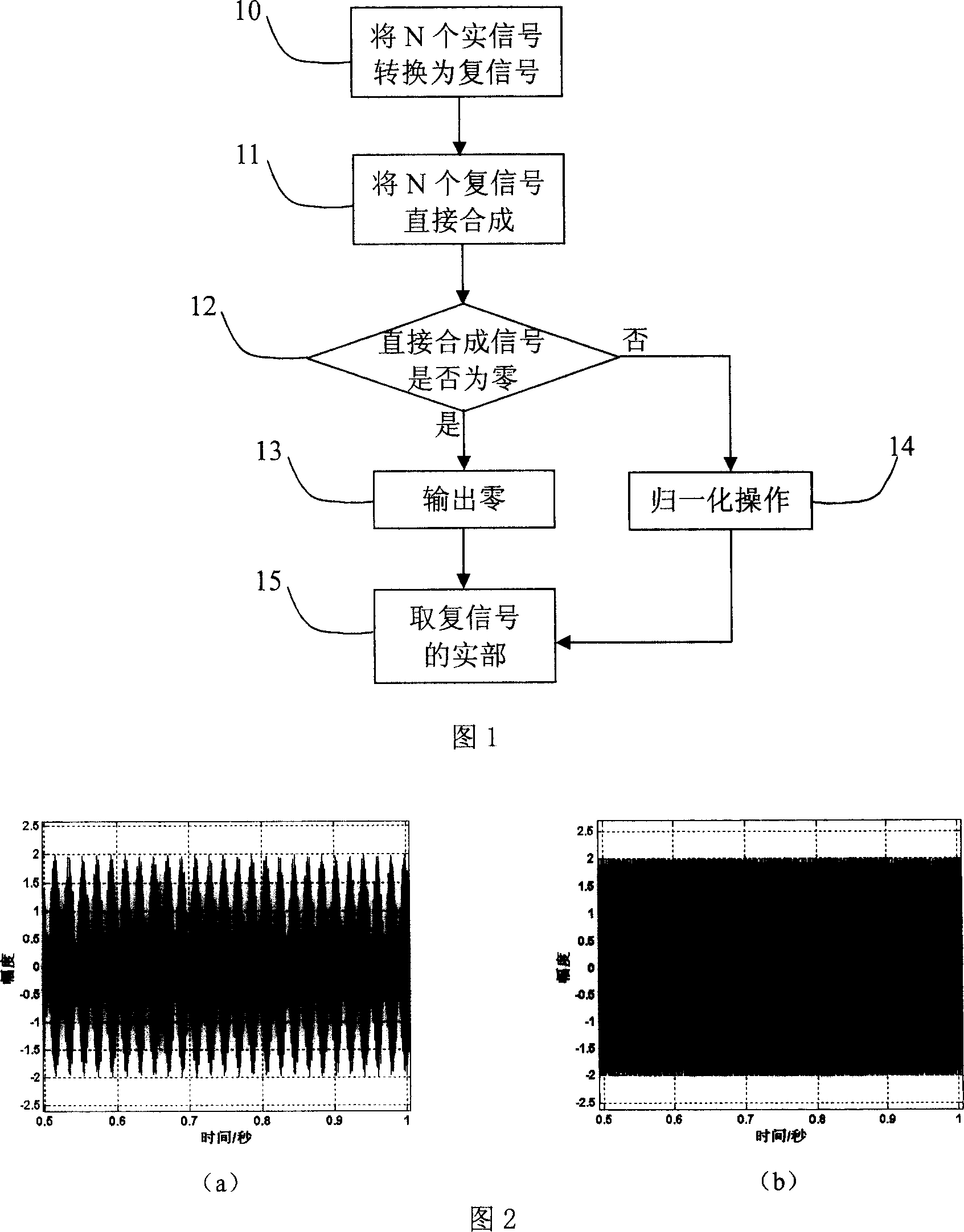
[0047] The present invention will be further described in detail below in conjunction with the accompanying drawings and specific embodiments.

[0048] As shown in Fig. 1, in step 10, in the present invention, the N (≥ 2) real signals to be synthesized are first converted into their corresponding complex signals. For N constant-amplitude real narrow-band modulation signals such as formula (1), the analytical signals or complex signals can be written as:

[0049] S 1 ( t ) = exp ( j ( 2 π f 1 t ...


PUM


Abstract

The invention discloses a multi-signal constant-envelope synthesizing method and device. The invention coverts many real signals into their corresponding complex signals, and then synthesize them all: if the directly synthesized complex signal is 0, the synthesized constant envelope complex signal is 0; otherwise, is normalized. The said device comprises signal converting module, directly synthesizing module, constant-envelope synthesizing module and real component drawing module, where the constant synthesizing module comprises a judging unit and a normalizing unit. The invention is simple and easy to apply and reduces the PAR of the synthesized signal to the minimum. On the condition of the same peak power, the effective signal component in the constant-envelope synthesized signal synthesized by the invention is greater than the directly synthesized signal, thus able to effectively raise communicating rate or distance. The synthesized signal of the invention keeps good relativity with all the signal components, and as compared with the directly synthesized signal, the relativity does not change.

Description

technical field [0001] The present invention relates to the field of communication, more specifically, to a constant-envelope signal synthesis method and a device thereof for a multi-signal superposition transmission communication mode. Background technique [0002] In the communication system, the commonly used signal is a real narrowband signal, recorded as: [0003] s(t)=a(t)cos(2πf 0 t+φ(t)) (1) [0004] where f 0 is the carrier frequency. For frequency modulation and modulation with constant amplitude, the information is contained in the phase φ(t), and the amplitude remains unchanged. Generally, a(t)=1 can be set, and its analytic signal or complex signal can be obtained as: [0005] S A (t)=exp(j(2πf 0 t+φ(t))) (2) [0006] It can be seen from the above formula that such a single communication signal is a constant envelope signal. [0007] In order to increase the communication rate, the method often used in communication is to superimpose and synthesize mult...

Claims


Application Information

Patent Timeline
Patent Type & Authority Patents(China)
IPC IPC(8): H04B1/04H04B15/00
Inventor 王海斌汪俊吴立新
Owner INST OF ACOUSTICS CHINESE ACAD OF SCI
Why Eureka
Try Eureka