
Method and apparatus for reducing PAR of beamforming output signals

a beamforming output signal and par reduction technology, applied in the field of 5 g communication, can solve the problems of high par, bler (block error rate), and high distortion of beamforming output signals, and achieve the effect of improving lte and 5g power control performance and par reduction

Active Publication Date: 2021-06-15
ALCATEL LUCENT SHANGHAI BELL CO LTD
View PDF5 Cites 0 Cited by
  • Summary
  • Abstract
  • Description
  • Claims
  • Application Information

AI Technical Summary

Benefits of technology

[0009]The objective of the present invention is to provide a method and apparatus for reducing PAR of beamforming output signals.
[0010]According to one aspect of the present invention, a method for reducing PAR of beamforming output signals, wherein input base band data is for N ports and number of beamforming output pipes is M;
[0024]According to one aspect of the present invention, an eNode B for reducing PAR of beamforming output signals, wherein input base band data is for N ports and number of beamforming output pipes is M;
[0029]The present invention enables a reduction on PAR of the beamforming output signals and then improves LTE and 5G power control performance.

Problems solved by technology

High PAR will bring high distortion to the signals in the beamforming output pipes and worsen the BLER (Block Error Rate), which is not allowed in LTE-A / 5G system.
Hence, the high PAR is a common problem for LTE-A / 5G system, which is brought by multi-layer beamforming use case.
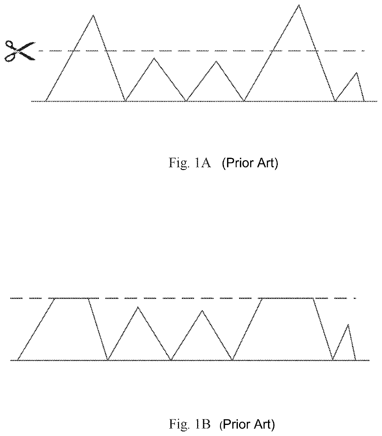
The CFR function in RF module can reduce the PAR by directly getting rid of the peak points, but it will make the signals distorted and worsen the BLER at the receiver side.
Thus CFR is not a good solution to deal with the high PAR problem.

Method used


Image

  • Method and apparatus for reducing PAR of beamforming output signals
  • Method and apparatus for reducing PAR of beamforming output signals
  • Method and apparatus for reducing PAR of beamforming output signals

Examples


Embodiment Construction

[0038]Hereinafter, the present invention will be further described in detail with reference to the accompanying drawings.

[0039]The present invention provides a solution of PAR reduction to minimize the PAR by introducing an optimal initial phase vector without signal wave distortion in time domain.

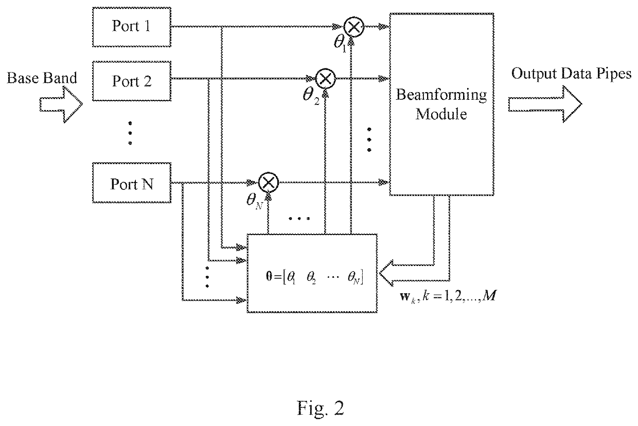
[0040]Specifically, weight vector θ for adjusting the phases of input base band data of each port is introduced to minimize the correlation of the input data of the N ports before beamforming.

[0041]Referring to FIG. 2, the number of input ports of base band signals is N, the number of output pipes of the beamforming module is M.

[0042]And the original input data for each port can be defined as data vector s, the adjusting weight vector θ can be defined as θ=[θ1 θ2 . . . θN].

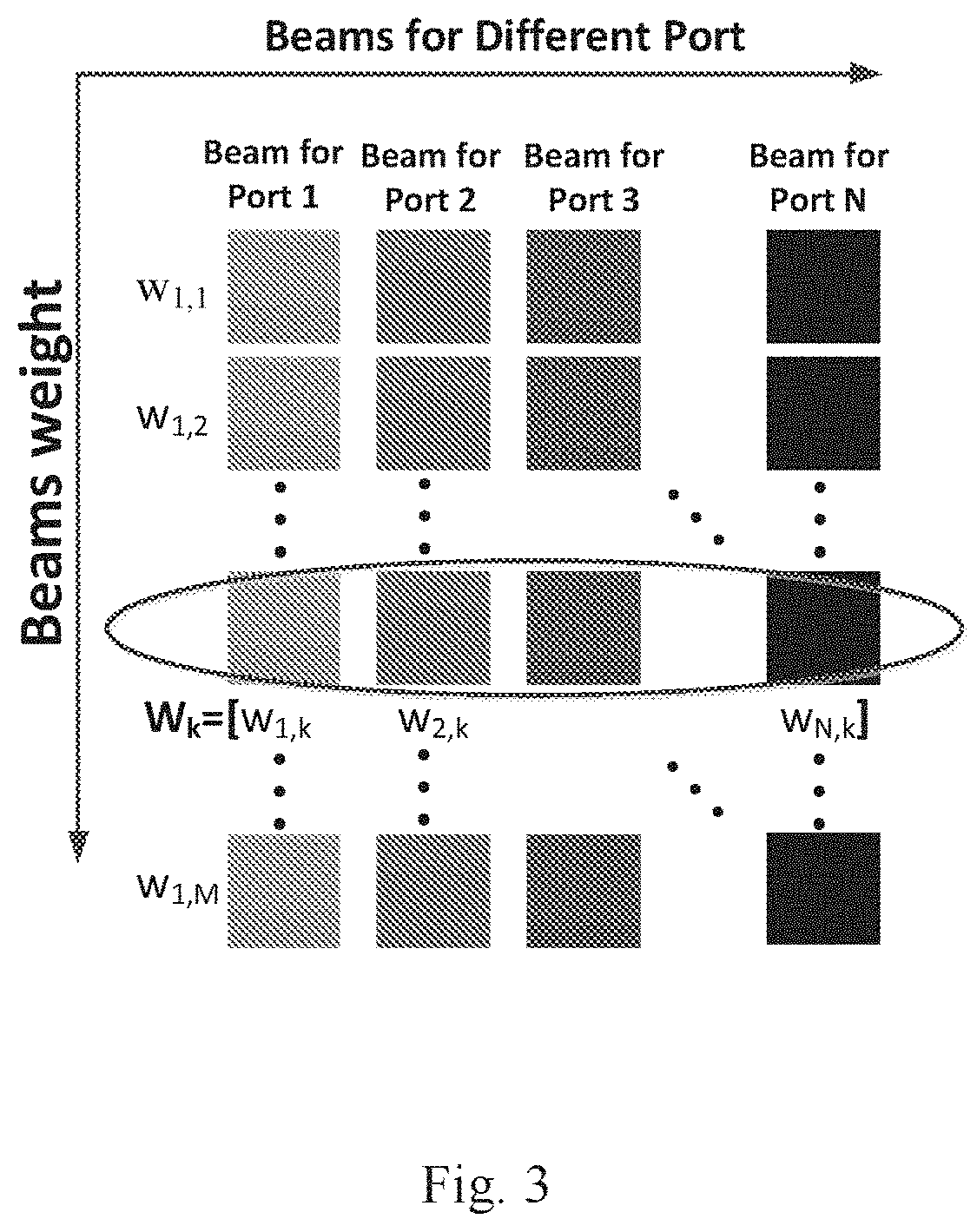
[0043]Beamforming weight vector wk is the weight vector of the total N beams for the k-th output pipe. And wk={w1,kw2,kw3,k . . . wN,k}, k=1, 2, . . . , M. FIG. 3 shows an exemplary schematic of wk.

[0044]It should be not...


PUM


Abstract

The objective of the present invention is to provide a method and apparatus for reducing PAR of beamforming output signals. A method for reducing PAR of beamforming output signals, wherein input base band data is for N ports and number of beamforming output pipes is M; wherein the method comprises the following steps: building a correlation matrix of the input base band data of the N ports; determining adjusting weight vector for the input data of each port in time domain based on the correlation matrix and wk being the beamforming weight vector of the total N beams for the k-th output pipe, to minimize the correlation of the input base band data of the N ports; adjusting the phase of the input data of each port in time domain based on the adjusting weight vector before beamforming. The present invention enables a reduction on PAR of the beamforming output signals and then improves LTE and 5G power control performance.

Description

CROSS-REFERENCE TO RELATED APPLICATIONS[0001]This application is a national phase under 35 U.S.C. § 371 of PCT International Application No. PCT / CN2017 / 111710 which has an International filing date of Nov. 17, 2017, the entire contents of each of which are hereby incorporated by reference.TECHNICAL FIELD[0002]The present invention relates to the technology of 5G communication, especially to reducing PAR of beamforming output signals.BACKGROUND OF INVENTION[0003]The beamforming technology is a significant strategy to get the beamforming gain, which has been widely used in the Massive-MIMO systems. But beamforming can also worsen the Peak to Average power Ration(PAR) of the beamforming module output pipes' signals, and the 1st pipe's PAR is the highest one because its weight vector w1=[1 1 1 1]T is full of 1.[0004]In LTE-A / 5G system, the PAR of the beamforming module output pipes can be very high, especially in the multi-layer space division multiplex scenarios.[0005]For example, in a...

Claims


Application Information

Patent Timeline
Patent Type & Authority Patents(United States)
IPC IPC(8): H04B7/06
CPCH04B7/0617H04L27/2615
Inventor CAI, ZHENHAOWANG, LEIZHAO, KUNSONG, YONG
Owner ALCATEL LUCENT SHANGHAI BELL CO LTD
Learn More