Developing device using toner and carrier mixture

A developing device and toner technology, which are applied in the direction of developer, electric recording process applying charge pattern, equipment of electric recording process applying electric charge pattern, etc., can solve problems such as inability to accommodate developer

Inactive Publication Date: 2007-11-21
RICOH KK
View PDF11 Cites 0 Cited by
  • Summary
  • Abstract
  • Description
  • Claims
  • Application Information

AI Technical Summary

Problems solved by technology

In this way, the developer on the developer carrier cannot accommodate the tone

Method used


Image

  • Developing device using toner and carrier mixture
  • Developing device using toner and carrier mixture
  • Developing device using toner and carrier mixture

Examples


no. 1 example

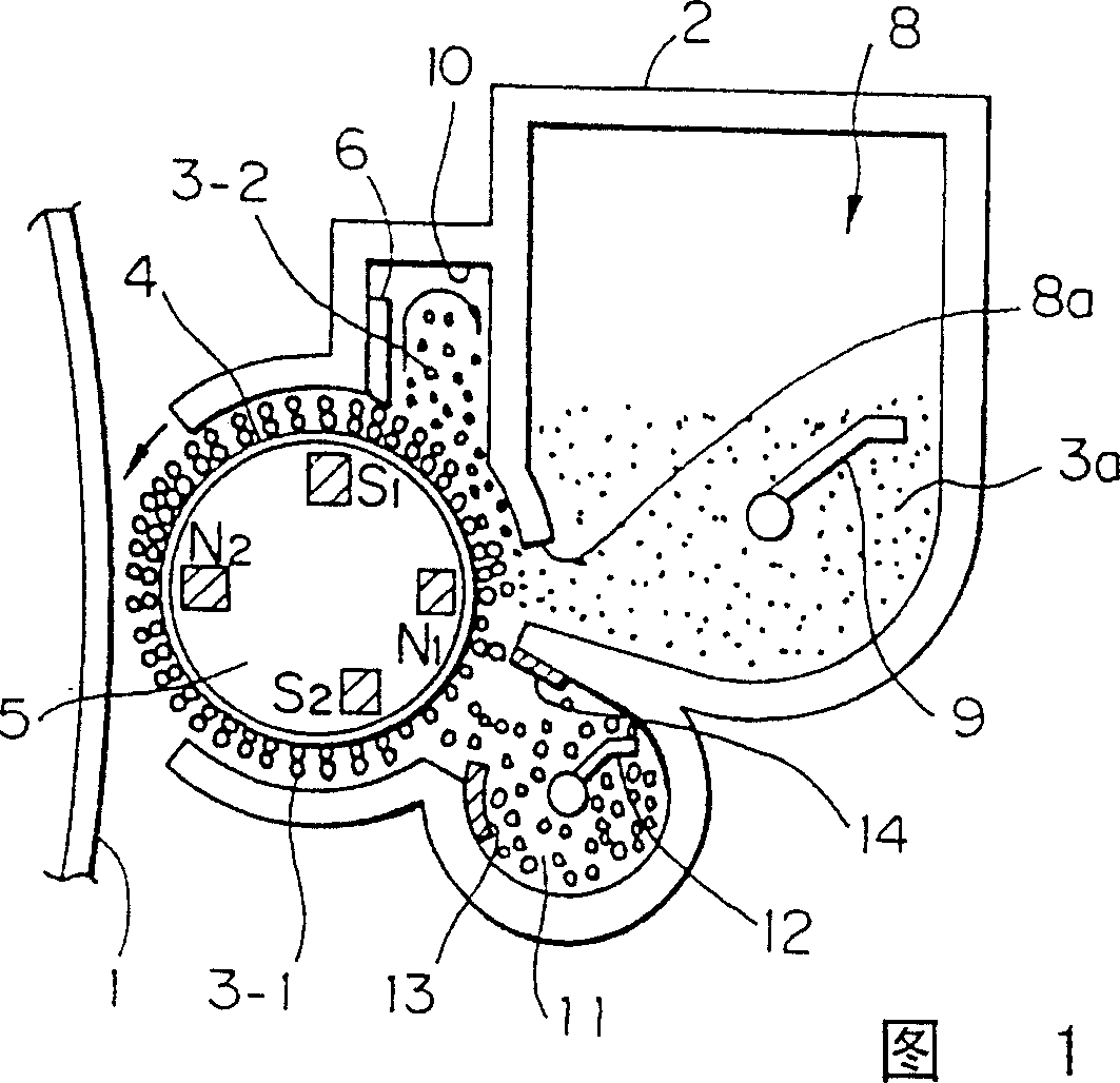
[0061] Referring to FIG. 1 , the developing device of the present invention includes a casing 2 . The case 2 may be located on one side of the image carrier 1 as a photoconductive drum, for example. The box 2 has an opening facing the carrier 1 . A developing sleeve or developer carrier 4 is deposited in the above-mentioned case 2 and partially exposed to the outside through the above-mentioned opening. A developer including magnetic toner and magnetic carrier remains on the surface of the above-mentioned sleeve 4 . Fixed in the sleeve 4 is a cylindrical magnet element or magnetic field generator 5 comprising a set of fixed magnets. A scraper or regulator 6 regulates the amount of developer deposited on the aforementioned sleeve 4 .

[0062]The inner side of the box body 2 is provided with a sleeve cavity for accommodating the above-mentioned sleeve 4, a developer storage cavity 10 for storing the developer scraped off by the scraper 6, a developer storage cavity 11, and a ...

example 1

[0097] First, use a hot roller at 120°C to melt and knead the mixture with the ingredients listed in Table 1 below, cool it to solidify, use a jet mill to pulverize the solidified body, and then sieve it to form an average particle size The toner particle a is 16 μm. The toner at 8.0 x 10 4 The saturation magnetization in a magnetic field of A / m is 60A.m 2 / kg.

[0098] Table 1

[0099] Styrene-acryloyl resin (Himer75 product available from Sanyo Kagaku company) 100 parts by weight

[0100] Carbon black (#44 product available from Mitsubishi kasei company) 5 parts by weight

[0101] Nigrosine dye (Nige color base EX product available from Orient company) 2 parts by weight

[0102] Tiny magnet particles (EPT-1000 product available from Toda kogyo company) 60 parts by weight

example 2

[0104] The procedure was the same as that of Toner Example 1 except that the mixture listed in Table 2 below was used, whereby Magnetic Toner b was prepared. The toner at 8.0 x 10 4 The saturation magnetization in a magnetic field of A / m is 20A.m 2 / kg.

[0105] Table 2

[0106] Styrene-acryloyl resin (Himer75 product) 100 parts by weight

[0107] Carbon black (#44 product) 5 parts by weight

[0108] Nigrosine dye (Nige color base EX product) 2 parts by weight

[0109] Tiny magnet particles (EPT-1000 product) 100 parts by weight


PUM

PropertyMeasurementUnit
Particle sizeaaaaaaaaaa
Thicknessaaaaaaaaaa
Weight average particle sizeaaaaaaaaaa

Abstract

In a developing device for an image forming apparatus and of the type using a developer consisting of toner and magnetic carrier, a toner hopper has an opening for replenishing toner stored therein. The developer is regulated by a doctor blade to form a thin layer on a developing sleeve. The developer scraped off by the doctor blade is introduced into a developer storing chamber and caused to move toward the opening of the hopper due to its own internal pressure and gravity. The developer taken in toner from the hopper is returned toward the doctor blade along the surface of the sleeve. The developer on the sleeve and regulated by the doctor blade is conveyed to a developing position where the sleeve faces an image carrier. The toner contained in the developer is a magnetic toner, When the toner concentration of the developer has reached an upper limit, a space or gap exists in the developer storing chamber.

Description

technical field [0001] The present invention relates to a developing device for a copier, facsimile machine, printer, or similar image forming apparatus. In particular, the present invention relates to a developing device of the type having a developer carrier in which a magnetic field generator is housed, said device allowing the developer carrier to convey a mixture of toner and magnetic carrier to , in which position the developer carrier faces the image carrier so as to develop the latent image formed on the image carrier. Background technique [0002] Generally, the image carrier electrostatically formed on the image carrier provided in the image forming apparatus is made by a toner, that is, a one-component type developer, or by a mixture of a toner and a magnetic carrier, that is, a two-component type developer. latent image development. In the above toner and carrier mixture, minute toner particles are electrostatically deposited on the surface of each relatively l...

Claims


Application Information

Patent Timeline
IPC IPC(8): G03G15/09G03G9/083G03G9/08G03G9/10G03G15/08
CPCG03G9/0821G03G9/08G03G2215/0609G03G9/083G03G15/0831G03G15/09G03G9/10G03G15/0839G03G15/0822G03G15/0849G03G15/0856G03G15/086G03G15/0877G03G15/0891
Inventor 冈诚二津田清典小山一佐佐木文浩望月贤加藤贵文
Owner RICOH KK
Why Eureka
Try Eureka