

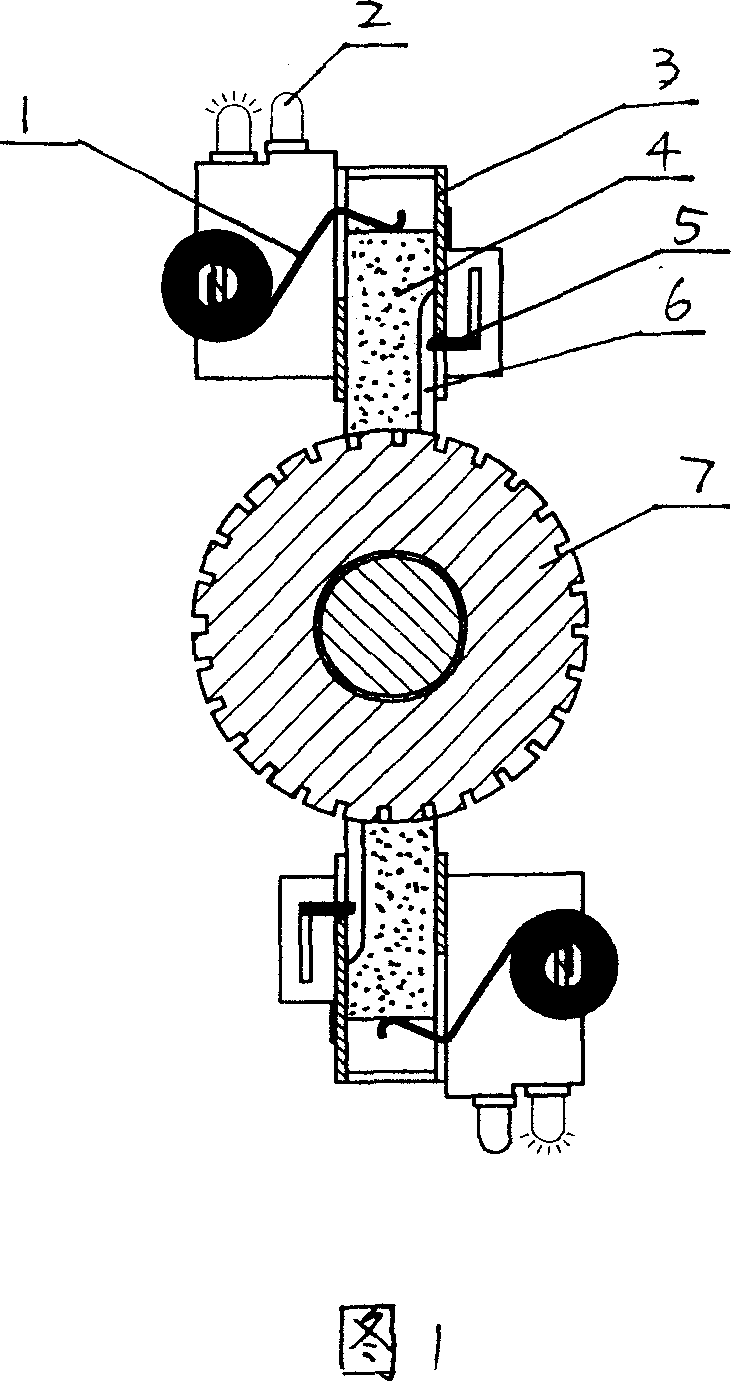
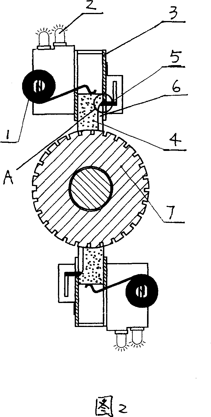
Carbon brush wear sensor device of motor
A technology of sensing devices and motors, applied in the direction of circuits, current collectors, electrical components, etc., can solve problems such as blocking the optical path, alarm failure, hole blockage, etc.
- Summary
- Abstract
- Description
- Claims
- Application Information
AI Technical Summary
Problems solved by technology
Method used
Image

Examples
Embodiment 1
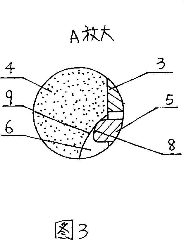
[0017] Embodiment 1 is that the surface of the carbon brush 4 is provided with a groove 6, the groove 6 extends along the sliding direction of the carbon brush 4, the conductive probe 5 is inserted in the groove 6, the The contact portion of the carbon brush 4 described above is the groove wall at the end of the groove 6 . The side of the end of the conductive probe 5 facing away from the moving direction of the carbon brush 4 is the probe arc surface 8. When the carbon brush 4 is in the second working state, the probe arc surface 8 and the carbon brush 4 are in the second working state. The contact parts of the carbon brushes 4 are in contact. The groove wall at the end of the groove 6 is a groove side arc surface 9 . Referring to FIG. 5 , there is a distance between the rear end of the groove 6 and the rear end of the carbon brush 4 , that is, there is still a distance between the end of the groove 6 and the rear end of the carbon brush 4 . When the end side of the carbon ...
Embodiment 2
[0018] Embodiment 2 Referring to FIG. 8 , the contact part of the carbon brush 4 is a metal conductive bump 10 whose root is embedded in the carbon brush 4 and whose outer end protrudes from the surface of the carbon brush 4 .
Embodiment 3
[0019] Embodiment 3 Referring to FIG. 9 , the contact portion of the carbon brush 4 is a raised carbon brush bump 12 provided on the surface of the carbon brush.
[0020] The sides of the outer ends of the conductive bump 10 of the second embodiment and the carbon brush bump 12 of the third embodiment facing the moving direction of the carbon brush 4 are also arc-shaped surfaces, which have the same function as the groove-side arc-shaped surface 9 .
PUM
 Abstract
Description
Claims
Application Information