Ultrasound transducer

A transducer and sound energy technology, which can be used in sound-generating devices, sound wave diagnosis, piezoelectric/electrostrictive transducers, etc., and can solve problems such as patient discomfort, injury to ultrasound machine operators, etc.

Inactive Publication Date: 2007-12-12
KONINKLIJKE PHILIPS ELECTRONICS NV
View PDF5 Cites 12 Cited by
  • Summary
  • Abstract
  • Description
  • Claims
  • Application Information

AI Technical Summary

Problems solved by technology

Increased pressure exerted by the sonographer will create patie

Method used


Image

  • Ultrasound transducer
  • Ultrasound transducer
  • Ultrasound transducer

Examples


Embodiment Construction

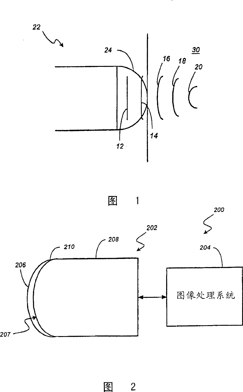
[0037] Conventional 1-dimensional (1-D) phased array transducers for ultrasound imaging typically include a lens to focus the acoustic beam sent by the transducer. In particular, the mechanical configuration of such lenses is usually chosen to focus the acoustic beam from the transducer in one vertical direction. The vertical dimension (direction) can also be focused mechanically, such as by making a concave shape on the transducer array. The transverse dimension (direction) is typically focused electronically.

[0038] As an example, conventional 1-dimensional (1-D) phased array transducers use a lens that causes transmitted acoustic energy to focus on an object, such as a human body. Typically, the lens material has an acoustic velocity less than that of the human body (approximately 1.5 mm / μsec (microsecond)). It is therefore assumed that the acoustic energy transmitted by the ultrasound transducer through the acoustic lens into the object tends to cover or focus within t...


PUM


Abstract

An acoustic imaging system is described. A preferred system includes a protective cover configured to mate with a transducer body. The transducer includes a two-dimensional transducer element matrix array formed by a plurality of individually controllable transducer elements. The protective cover is superposed above the two-dimensional matrix array and is transparent to incident acoustic energy. Preferably, the protective cover is shaped to reduce patient discomfort and repetitive motion injuries to sonographers. Alternative embodiments comprise a shaped two-dimensional transducer element matrix array. Methods for improved ultrasound imaging are also provided.

Description

[0001] Cross-references to related applications [0002] This application claims priority to co-pending U.S. Patent Application Serial No. 60 / 301,282, filed June 27, 2001, entitled "Improved Ultrasonic Transducer," the entire contents of which are incorporated in This is for reference. technical field [0003] This application relates generally to acoustic imaging. More specifically, the present application relates to ultrasound imaging systems and methods using transducers having a two-dimensional array of transducer elements. Background technique [0004] Ultrasound imaging systems have become important diagnostic tools in many medical subjects. A great advantage of ultrasound imaging systems is real-time scanning. For example, an ultrasound imaging system can produce images so quickly that the operator of the ultrasound machine can scan internal organs or identify movement in the body, such as blood flow, in real time, interactively, and with visual feedback. This al...

Claims


Application Information

Patent Timeline
IPC IPC(8): G01S15/00G01N29/24A61B8/00A61B8/06G01S7/521G01S15/89G10K11/02G10K11/34H04R17/00
CPCG01S15/8925A61B8/06A61B2562/0204G01S15/8927G10K11/02G01S15/892A61B8/13G01S7/52079G10K11/34A61B2562/046A61B8/4281A61B8/4494A61B8/00
Inventor W·J·奥斯曼
Owner KONINKLIJKE PHILIPS ELECTRONICS NV
Why Eureka
Try Eureka