Improved magnetic force booster

A booster and magnetic technology, applied in the field of improved magnetic booster, can solve problems such as not being able to get close enough, the impact of the booster effect, and difficulty in approaching

Inactive Publication Date: 2007-12-12
郭天桥 +2
View PDF2 Cites 0 Cited by
  • Summary
  • Abstract
  • Description
  • Claims
  • Application Information

AI Technical Summary

Problems solved by technology

However, in actual manufacture and use, the setting of the static magnet, that is, the booster magnet, has the technical defect that the booster is too small
After analysis and research, the reason for the small increase in force is that the repulsive force between the stationary magnet and the magnetic slider is not fully exerted. When the magnetic slider moves upwards, it is difficult to get close to the two due to the repulsive effect of the repulsive force field or cannot fully Closer, therefore, the boost effect obtained by pushing out using the static magnetic repulsion is affected

Method used


Image

  • Improved magnetic force booster
  • Improved magnetic force booster

Examples


Embodiment Construction

[0020] The present invention will be further described in detail below in conjunction with the accompanying drawings.

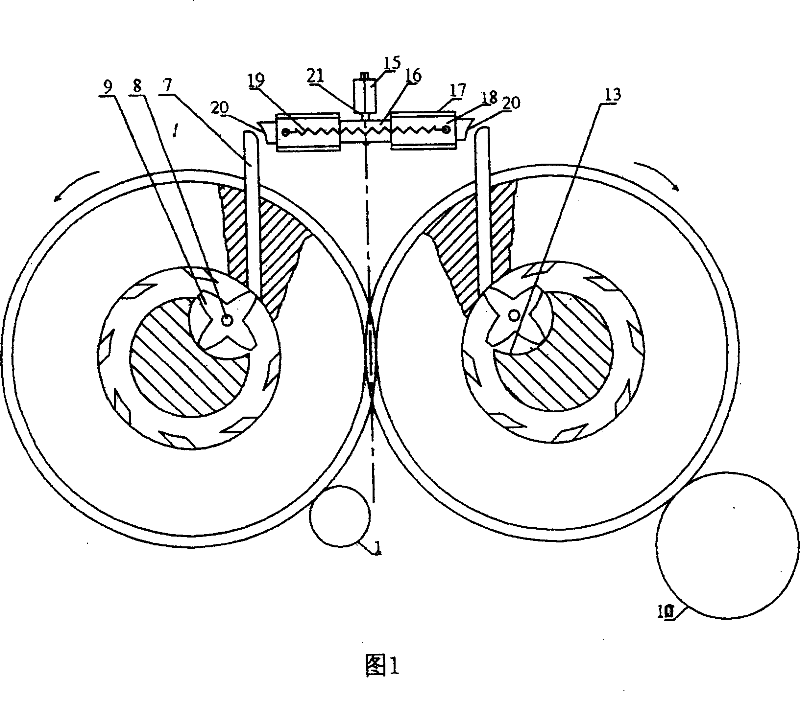
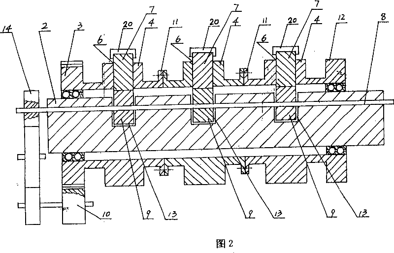
[0021] As shown in Fig. 1, a kind of improved magnetic booster of the present invention, comprises driving device 1, two mutually parallel main shafts 2, is provided with main shaft gear 3 respectively on two main shafts 2 and two gears mesh with each other, in two Each main shaft 2 is respectively provided with one group or more than one group of non-magnetic runners 4, and the main shaft gear 3 and the runners 4 are connected as one (see Fig. The moving booster magnet 20, the booster magnet 20 reciprocates under the action of the cam 16, is provided with several chutes 6 on the runner, and is provided with a magnetic slider 7 inside the chute 6, and the bottom of the chute 6 slot A tension spring is provided to connect with the tail of the magnetic slider 7, the polarity of the head of the magnetic slider 7 is the same as that of the corresponding end of th...


PUM


Abstract

This invention provides an improved magnetic power machine including orderly extended several pairs of magnetic slide blocks uniformly distributed on the oppositely rotating wheels, a power magnet opposite to the pole of said magnet slide block is set correspondingly in the space held by each pair of magnetic blocks when extending from their own slots characterizing that the power magnet is fixedly connected with the to-and-fro operating unit.

Description

technical field [0001] The invention relates to a magnetic booster, in particular to an improved magnetic booster. Background technique [0002] In the past, in general mechanical power devices, when the driving force needs to be increased, the power of the engine is often required to increase, which can achieve the purpose of increasing power, but consumes a lot of materials and energy, and will cause environmental pollution. In view of this situation, the inventor designed a magnetic booster according to the principle of magnetic force, and applied for a Chinese patent in 2002, the patent number of which was 02244221.9. In this patent, the design structure of the magnetic booster is described in detail. In this structure, a pair of identical intermeshing gears respectively drive the same two sets of runners to rotate in opposite directions, and several sliding wheels are evenly distributed on each runner. There is a magnetic slider in each chute, and when the magnetic sli...

Claims


Application Information

Patent Timeline
Patent Type & Authority Patents(China)
IPC IPC(8): H02K51/00H02N11/00F16H49/00
Inventor 郭天桥郭春茂郭全才
Owner 郭天桥
Why Eureka
Try Eureka