

Improved magnetic force booster
A technology of booster and magnetic force, which is applied in the field of improved magnetic booster, and can solve the problems of static magnets, that is, booster magnets with small booster force, inability to get close enough, and influence of booster effect, etc.
- Summary
- Abstract
- Description
- Claims
- Application Information
AI Technical Summary
Problems solved by technology
Method used
Image

Examples
Embodiment Construction
[0020] The present invention will be further described in detail below in conjunction with the drawings.
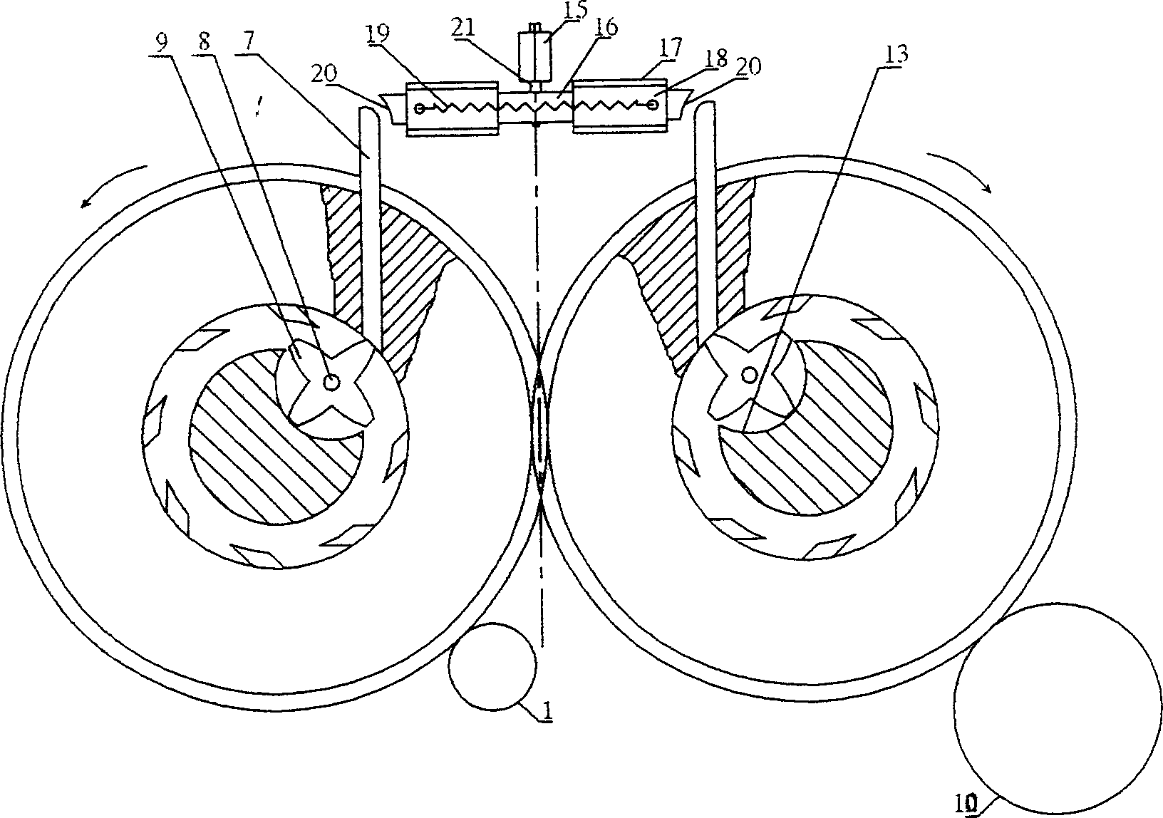
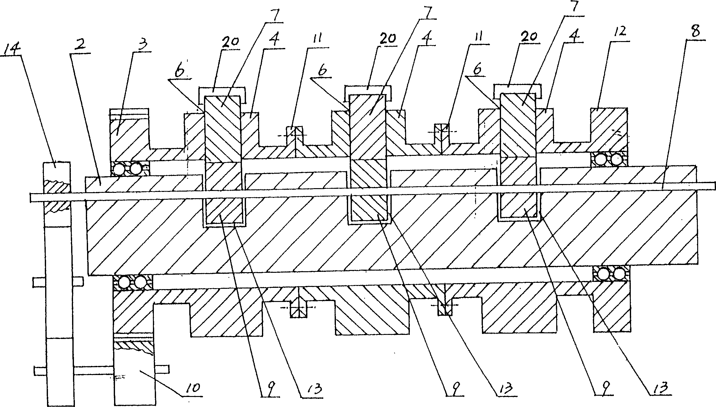
[0021] Such as figure 1 As shown, an improved magnetic booster of the present invention includes a driving device 1, two parallel main shafts 2, on the two main shafts 2 are each provided with a main shaft gear 3 and the two gears mesh with each other, on the two main shafts 2 Each is provided with one or more sets of non-magnetic runners 4, and the main shaft gear 3 and runners 4 are connected to each other as a whole (see figure 2 ), the upper part of each group of runners is provided with a booster magnet 20 capable of reciprocating movement, and the booster magnet 20 reciprocates under the action of the cam 16. There are several sliding grooves 6 on the runners, and the sliding grooves 6 A magnetic slider 7 is arranged inside, and a tension spring is provided at the bottom of the slot of the sliding groove 6 to connect with the tail of the magnetic slider 7. The polarity...
PUM
 Abstract
Description
Claims
Application Information