Device for electronically contacting an electrically conductive part of a high-frequency system

A technology of conductive parts and electrical contact, applied in the direction of two-part connection device, parts of the connection device, contact parts, etc., can solve the problems of corrosion, brass stress corrosion, etc.

Inactive Publication Date: 2007-12-19
托马斯・康茨
View PDF4 Cites 0 Cited by
  • Summary
  • Abstract
  • Description
  • Claims
  • Application Information

AI Technical Summary

Problems solved by technology

But brass has the disadvantage of stress corrosion cracking, so when the devices are used outdoors, especially when they are installed in wet, dirty environments, they must be additionally protected by insulating tape or shrink-fit tubes to avoid external Erosion Effects of the Environment
This creates additional overhead when installing

Method used


Image

  • Device for electronically contacting an electrically conductive part of a high-frequency system
  • Device for electronically contacting an electrically conductive part of a high-frequency system

Examples


Embodiment Construction

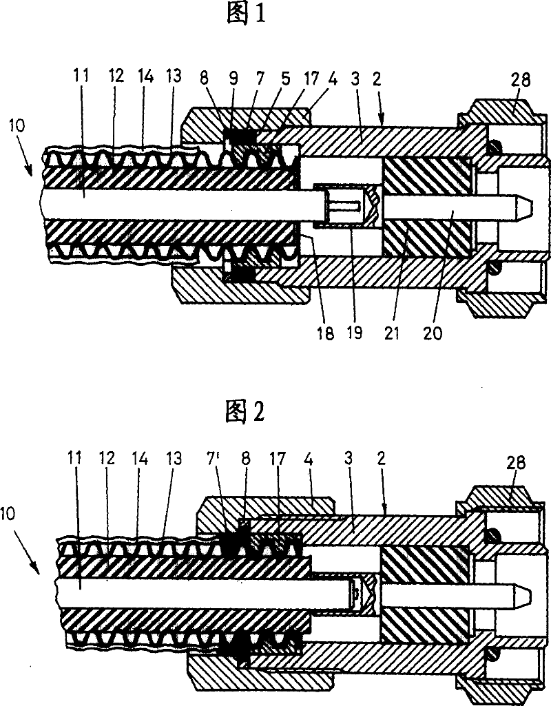
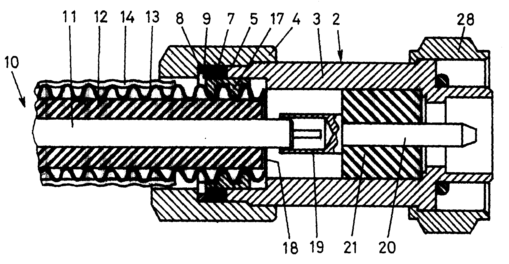
[0009] According to FIGS. 1 and 2 , the high-frequency component is a coaxial plug 2 which has a housing 3 on which a coaxial cable 10 is detachably fastened by means of nuts 4 . The coaxial cable 10 has, in known manner, an inner conductor 11 , an insulator 12 , a corrugated tube sheath 13 as outer conductor, and an outer jacket 14 . The inner conductor 11 is connected via the connecting sleeve 9 to a plug pin 20 which is surrounded by an insulator 21 . The coaxial plug 2 is screwed by a further nut 28 to a plug part (not shown here).

[0010] In FIG. 1 , the nut 4 has not been completely screwed onto the housing 3 . During the further screwing of the nut 4 into the position shown in FIG. 2 , a seal 7 , for example made of synthetic rubber, partially enters an annular space 9 so that a threaded ring screwed onto the bellows sheath 13 17 is isolated and sealed from the outside world. As shown in the figure, the front end of the bellows sheath 13 is deformed during screwing ...


PUM


Abstract

A high-frequency component includes at least one metallic supporting element which is made of bronze, particularly cast bronze (3,4,28). The proportion of zinc is less than 18 percent by weight, preferably less than 12 percent by weight. The component is substantially more resistant in an aggressive atmosphere, especially to ammonia and sulfur compounds, than brass.

Description

technical field [0001] The invention relates to a device for making electrical contact with electrically conductive components of a high-frequency system. Background technique [0002] For the electrical contact eg with coaxial cables, stainless steel according to the international standard "Fed.Spec.QQ-S-764" is used in high-frequency technology. However, this type of steel produces unwanted intermodulation products, making it unusable in many high-frequency applications. As an alternative to the steel mentioned above, brass conforming to the "QQ-B-626" standard can also be used. But brass has the disadvantage of stress corrosion cracking, so when the devices are used outdoors, especially when they are installed in wet, dirty environments, they must be additionally protected by insulating tape or shrink-fit tubing to avoid external Erosion effects of the environment. This creates additional overhead at install time. Contents of the invention [0003] It is an object o...

Claims


Application Information

Patent Timeline
IPC IPC(8): H01R13/646C22C9/04H01R13/03
CPCH01R13/03H01R24/564H01R13/52H01R24/48H01R24/56H01R2103/00H01R24/40H01R13/646
Inventor 托马斯·康茨
Owner 托马斯・康茨
Why Eureka
Try Eureka