Computer interface cark

A computer interface and computer technology, which is applied in the field of computer interface cards, can solve problems such as EMI, electromagnetic interference, and antenna effects caused by cables, and achieve the effect of preventing EMI problems

Inactive Publication Date: 2008-01-09
AVERMEDIA TECH
View PDF3 Cites 0 Cited by
  • Summary
  • Abstract
  • Description
  • Claims
  • Application Information

AI Technical Summary

Problems solved by technology

[0004] However, since the TV cable is a sensitive noise conduction path, when the TV cable reaches a certain length, it will have an antenna effect
In this way, the noise of the laptop is easily brought out by the TV cable through the TV card, and accumulated on the TV cable
Therefore, electromagnetic interference (EMI) problems occur, which cannot meet the standards of regulations
As for other electronic products using PCMCIA, Card Bus or Express Card bus interfaces, such as computer interface cards connected to cables, the cables will also bring noise out of the computer and accumulate on the cables, causing the cables to also generate EMI question

Method used


Image

  • Computer interface cark
  • Computer interface cark
  • Computer interface cark

Examples


Embodiment 1

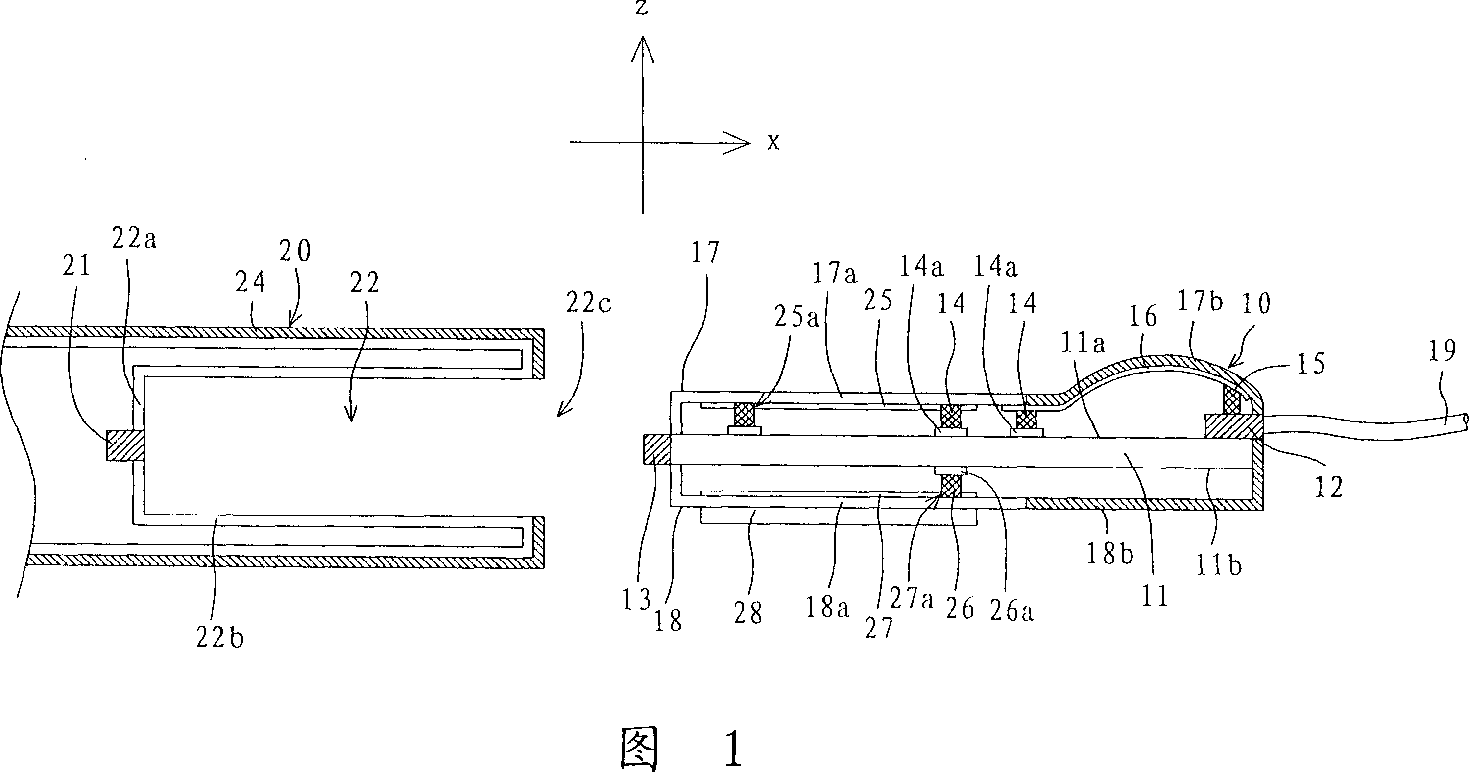
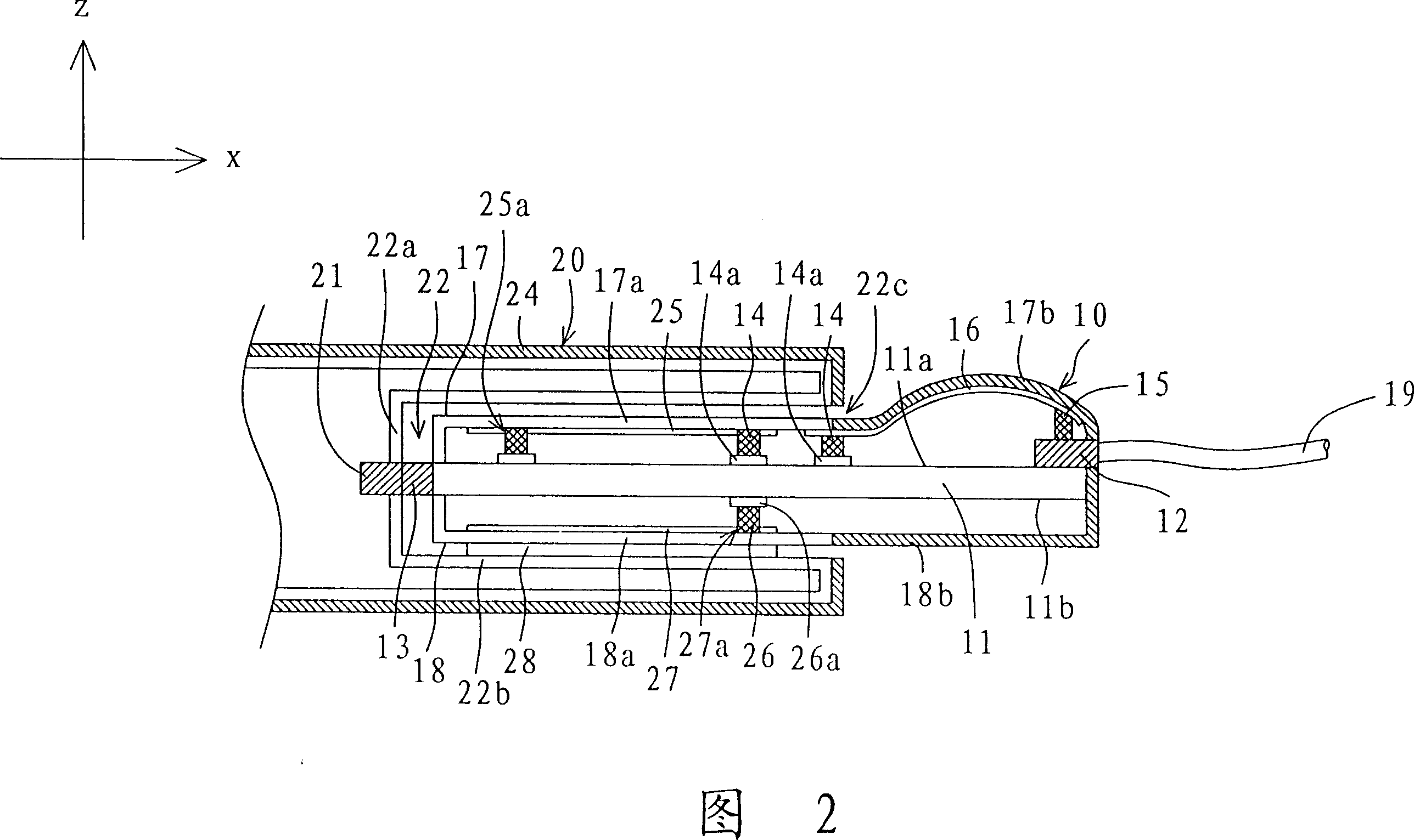
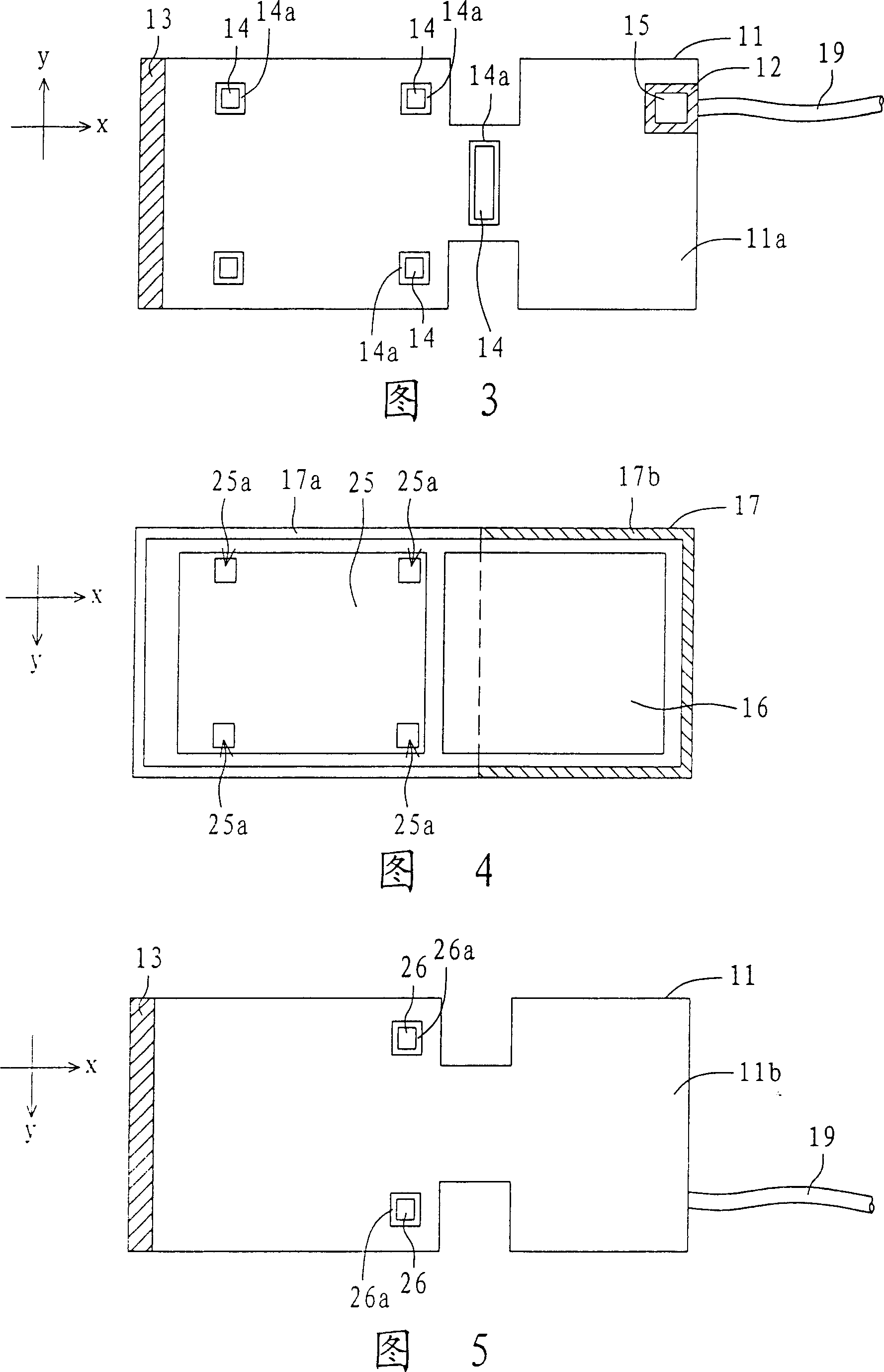
[0023] Please refer to FIGS. 1-7 at the same time. FIG. 1 is a separate sectional view of the computer interface card and the computer according to the first embodiment of the present invention, and FIG. 2 is a combined sectional view of the computer interface card and the computer according to the first embodiment of the present invention. In addition, Fig. 3 is a top view of the circuit board of the computer interface card of Fig. 1, Fig. 4 is a bottom view of the upper cover of the computer interface card of Fig. 1, and Fig. 5 is a bottom view of the circuit board of the computer interface card of Fig. 1 . In addition, FIG. 6 is a top view of the base of the computer interface card in FIG. 1 , and FIG. 7 is a bottom view of the base of the computer interface card in FIG. 1 . In FIGS. 1-2 , the computer interface card 10 disclosed in this embodiment is at least connected to a cable 19 and a computer 20 , and receives an analog or digital video signal through the cable 19 . A...

Embodiment 2

[0037] Please refer to FIG. 8 , which is a top view of the circuit board of the computer interface card according to the second embodiment of the present invention. In Fig. 8, the difference between the computer interface card 80 of this embodiment and the computer interface card 10 of Embodiment 1 is that a fourth connector 82 and a fourth connector 82 are also arranged on the upper surface 11a of the circuit board 11 in this embodiment For the fourth upper conductor 85 , the rest of the same constituent elements continue to use the reference numerals and will not be repeated here.

[0038] As shown in FIG. 8 , the fourth connector 82 is adjacent to the first connector 12 and is electrically connected to the second connector 13 through the inner circuit of the circuit board 11 . The fourth upper conductor 85 is disposed on the metal shell of the fourth connector 82 , such as a conductive sponge. When the upper cover 17 and the base 18 of FIGS. 4 to 5 are snapped together to ...

Embodiment 3

[0042]Please refer to FIG. 9 , which is a top view of the circuit board of the computer interface card according to the third embodiment of the present invention. In Fig. 9, the difference between the computer interface card 90 of the present embodiment and the computer interface card 80 of the second embodiment is that a fifth connector 92 and a fifth connector 92 and a For the fifth upper conductor 95 , the rest of the same constituent elements continue to use the reference numerals and will not be repeated here.

[0043] As shown in FIG. 9 , the fifth connector 92 is adjacent to the fourth connector 82 and is electrically connected to the second connector 13 through the inner circuit of the circuit board 11 . The fifth upper conductor 95 is disposed on the metal shell of the fifth connector 82 , such as a conductive sponge. When the upper cover 17 and the base 18 of FIGS. 4 to 5 are snapped together to sandwich the circuit board 11 of FIG. The third upper conductor 16 in ...


PUM


Abstract

The computer interface card includes a circuit board, a first connector, a second connector, first conductors, a second conductor, a third conductor, an upper cover and a base. Being setup a side of the circuit board, the first connector is in use for connecting to a cable. Being setup the other side of the circuit board, the second connector is in use for connecting to the third conductor and first conductors electrically. Transmission interface between second and third conductors includes PCMCIA, Card Bus or Express Card bus interface. The first conductor is connected to ground terminal of the circuit board electrically, and the second conductor is connected to metal case of the first connector. The upper cover and the base are in clip connection so as to clip the circuit board. The upper cover and the base possess an upper metal cover and a lower metal base. The upper metal cover is connected to the first conductors and the lower metal base electrically.

Description

technical field [0001] The invention relates to a computer interface card. Background technique [0002] In today's era of rapid technological development, computers have become an indispensable part of modern people's daily life. Because computers can only play digital audio-visual signals, the analog TV audio-visual signals currently output by TV stations cannot be directly played on computers. Therefore, some operators have developed an audio-visual signal transmission and processing device to encode the analog TV audio-visual signal into a digital audio-visual signal that can be played by a computer. [0003] Currently, the audio-video signal transmission and processing device widely used in the market is, for example, a TV tuner card or a TV capture card, through which a user can watch TV signals on a computer screen. However, common TV cards are all PCI interfaces, which are mainly used in desktop computers, and do not have the function of hot plug. On the other han...

Claims


Application Information

Patent Timeline
Patent Type & Authority Patents(China)
IPC IPC(8): G06F1/16H01R12/00
Inventor 林大钧林勇达蔡入伟
Owner AVERMEDIA TECH
Why Eureka
Try Eureka