Heat-conducting plate with wick supporting structures and method for manufacturing same

The technology of a support structure and manufacturing method is applied in the field of heat conduction plate with capillary support structure and its production, which can solve the problems of long return path, lack of capillary structure, and influence on heat transfer effect of heat conduction plate, so as to achieve enhanced heat transfer effect, The effect of shortening the return path

Active Publication Date: 2010-10-20
NIDEC CHAUN-CHOUNG TECH CORP
View PDF5 Cites 0 Cited by
  • Summary
  • Abstract
  • Description
  • Claims
  • Application Information

AI Technical Summary

Problems solved by technology

[0004] However, in the past, the heat conduction plate only has a capillary structure attached to the inner wall of its cover plate, and does not have any capillary structure on the surface of the support structure supported between the two cover plates.
Therefore, when the known working fluid inside the heat conduction plate is undergoing a phase change, the liquid working fluid can only flow back to the bottom of the inner wall of the heat conduction plate after the top of the inner wall of the heat conduction plate flows toward the inner wall of the periphery, which will cause backflow The path is long, which affects the heat transfer effect of the heat conduction plate

Method used


Image

  • Heat-conducting plate with wick supporting structures and method for manufacturing same
  • Heat-conducting plate with wick supporting structures and method for manufacturing same
  • Heat-conducting plate with wick supporting structures and method for manufacturing same

Examples


Embodiment Construction

[0040] In order to enable those skilled in the art to further understand the characteristics and technical content of the present invention, please refer to the following detailed description and accompanying drawings of the present invention. However, the accompanying drawings are provided for reference and illustration only, and are not intended to limit the present invention. .

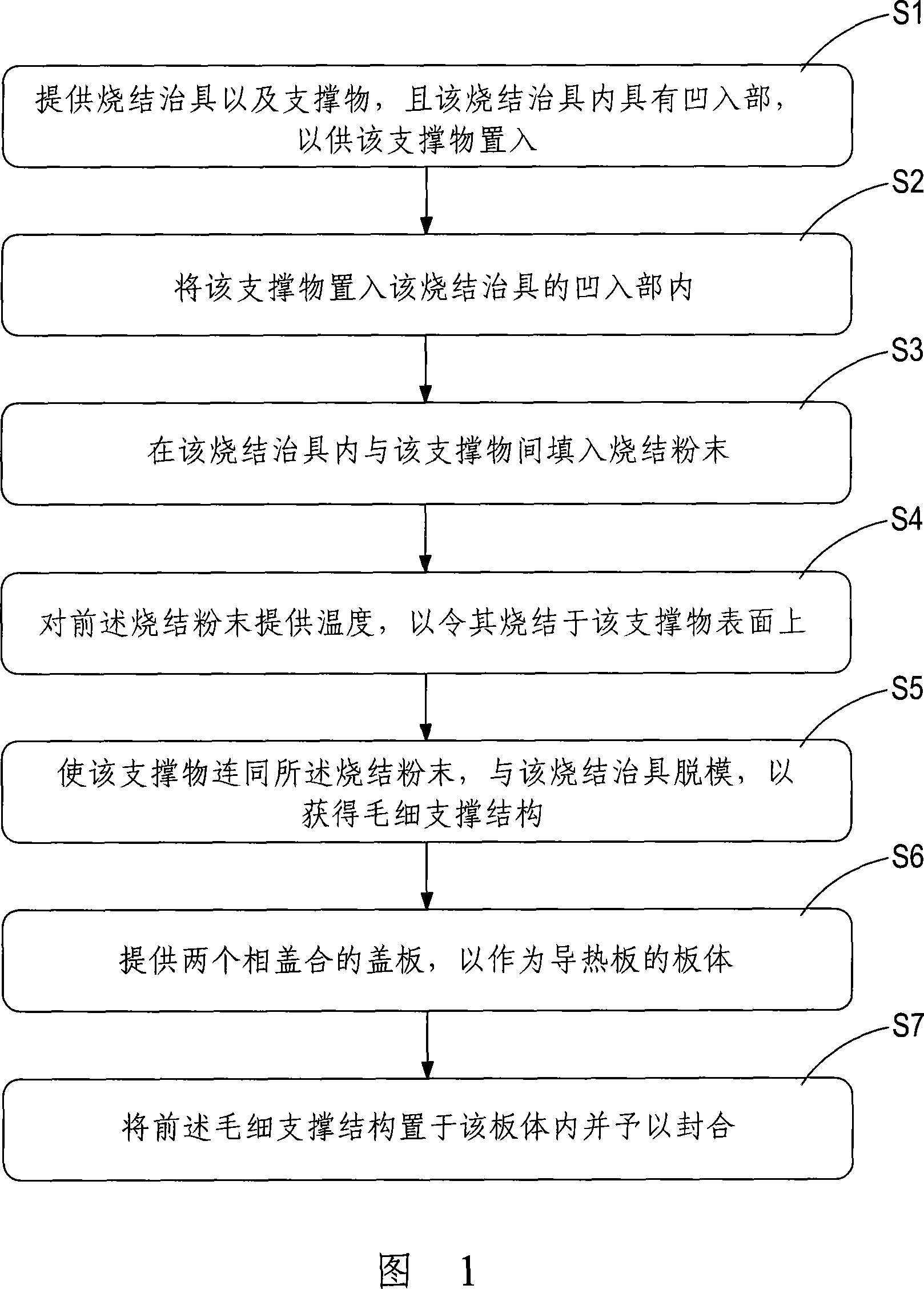
[0041] see figure 1 Shown is the flow of steps of the manufacturing method of the present invention. The invention provides a heat conducting plate with a capillary support structure and a manufacturing method thereof. The manufacturing method steps are as follows:

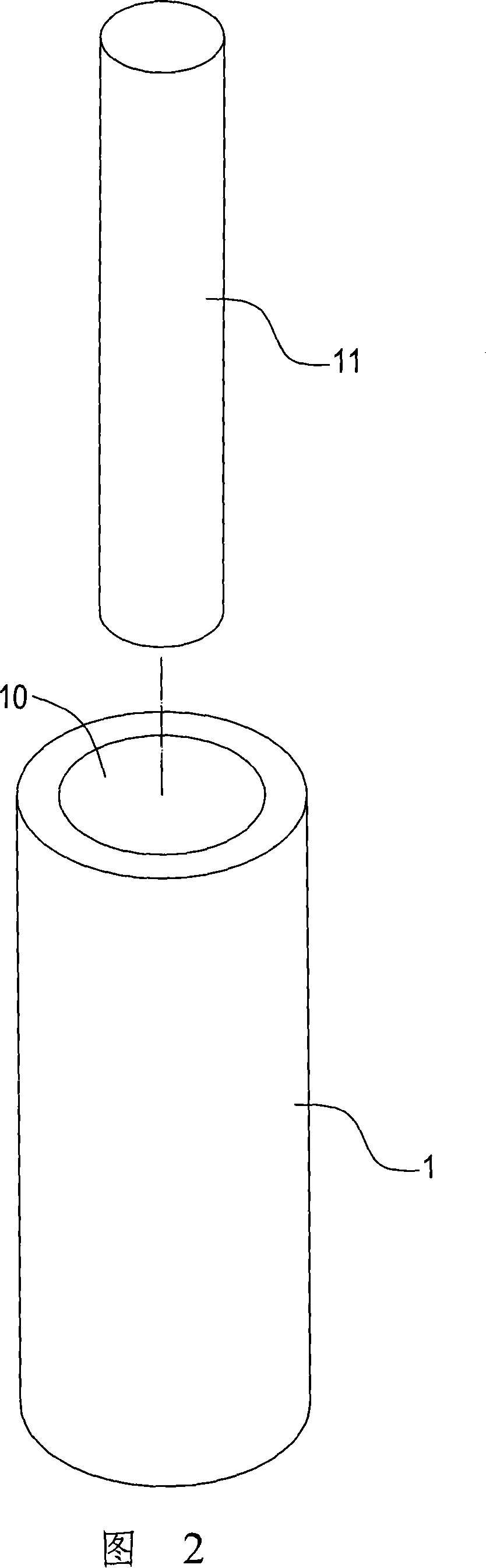
[0042] Step S1: providing a sintering jig and a support, and the sintering jig has a concave part for the support to be placed in;

[0043] Step S2: placing the support into the concave portion of the sintering jig;

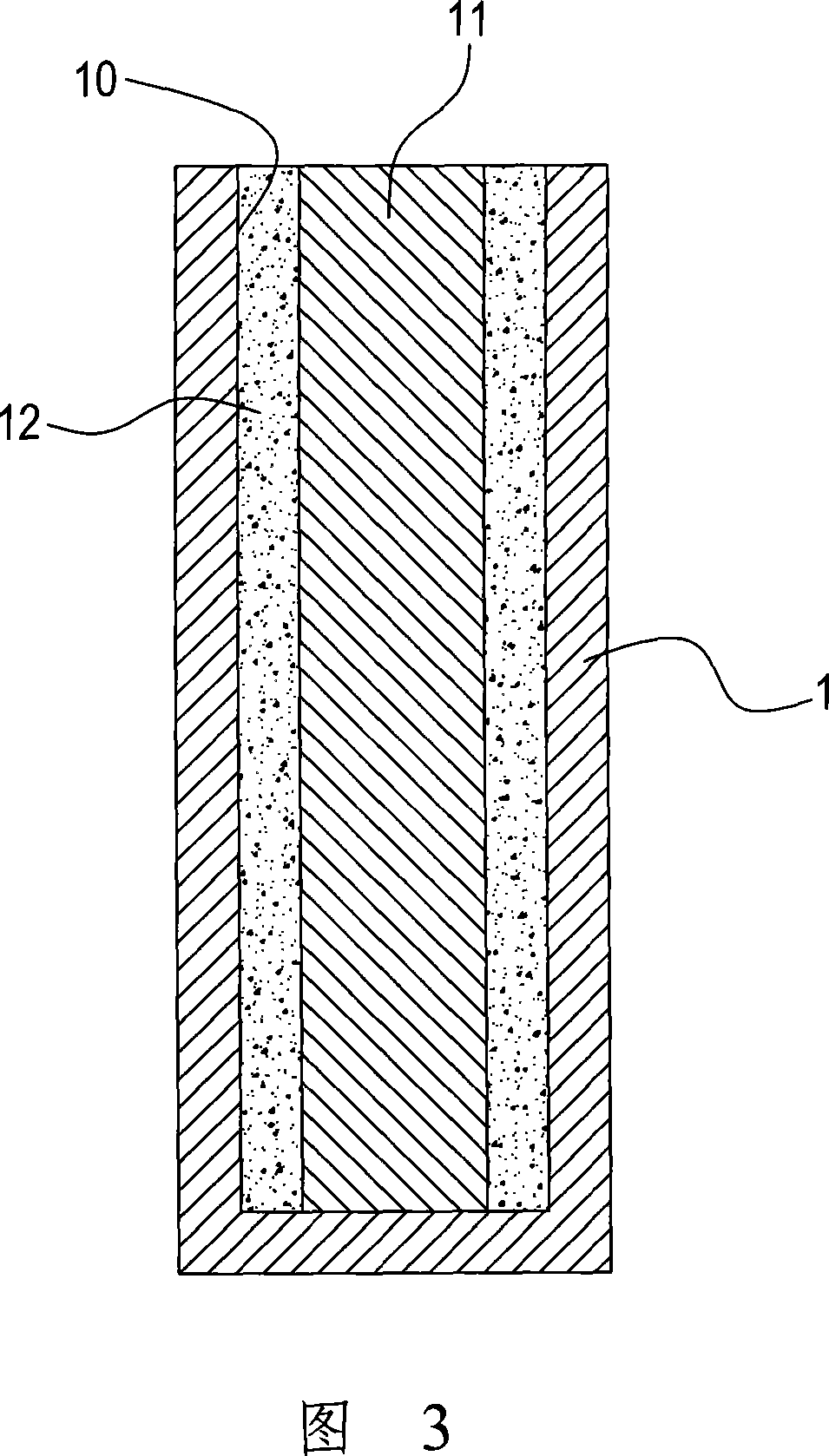
[0044] Step S3: Filling sintering powder between the sintering fixture and the support;

[0045] Step S4: providing...


PUM


Abstract

The invention provides a heat-conducting plate with wick supporting structures, which comprises a hollow plate body and two or more wick supporting structures, wherein the internal wall of the plate body is attached with wick tissues, the wick supporting structures vertically support and are uniformly distributed inside the plate body and in a cylindrical shape and the circumferential surfaces ofthe cylinder shapes are provided with sintered powder wick which contacts the wick tissues attached to the inner wall of the plate body so as to form a wick flow pass. Moreover, the invention also provides a method for manufacturing the heat-conducting plate with the wick supporting structures. The supporting structure inside the heat-conducting plate also has wick tissues which allow working fluid to flow back smoothly to improve the heat transfer effect of the heat-conducting plate.

Description

technical field [0001] The invention relates to a heat conduction technology, in particular to a capillary support structure inside a heat conduction plate and a manufacturing method thereof. Background technique [0002] At present, the heat conduction plate is a kind of plate-shaped heat pipe. Its principle is the same as that of the heat pipe. It passes through the internal vacuum environment to provide the working fluid injected into it. And return to liquid state, to recycle after reflux. [0003] However, heat spreaders and heat pipes are manufactured differently. The tube body of the heat pipe is usually in the shape of a tube. The tube body can be closed at one end first, and then perform operations such as injecting working fluid, degassing or vacuuming through the other open end. At the moment when the degassing is completed, the tube body is immediately closed, that is The production of the heat pipe can be completed. The plate body of the heat conduction plate...

Claims


Application Information

Patent Timeline
Patent Type & Authority Patents(China)
IPC IPC(8): F28D15/02B22F7/08
Inventor 王证都廖邦宏
Owner NIDEC CHAUN-CHOUNG TECH CORP
Why Eureka
Try Eureka