Heat radiating capillary structure, heat conducting component and method for making the heat radiating capillary structure

A capillary structure and fine structure technology, applied in cooling/ventilation/heating transformation, electrical components, electric solid devices, etc. Problems such as poor heat flow density, etc., to achieve good heat transfer performance

Inactive Publication Date: 2008-04-16
艾建华
View PDF0 Cites 5 Cited by
  • Summary
  • Abstract
  • Description
  • Claims
  • Application Information

AI Technical Summary

Problems solved by technology

[0008] It can be seen from the above table that the mesh core structure has good capillary force, but its permeability, thermal resistance, capillary limit at 0° inclination, gravity-affected capillary limit, flux density (boiling limit) and reliability are all poor.
The sintered powder core structure has good capillary force, heat flux density (boiling limit), gravity-affected capillary limit and reliability,

Method used


Image

  • Heat radiating capillary structure, heat conducting component and method for making the heat radiating capillary structure
  • Heat radiating capillary structure, heat conducting component and method for making the heat radiating capillary structure
  • Heat radiating capillary structure, heat conducting component and method for making the heat radiating capillary structure

Examples


Embodiment Construction

[0024] In order to make the technical problems, technical solutions and beneficial effects to be solved by the present invention clearer, the present invention will be further described in detail below in conjunction with the accompanying drawings and embodiments. It should be understood that the specific embodiments described here are only used to explain the present invention, not to limit the present invention.

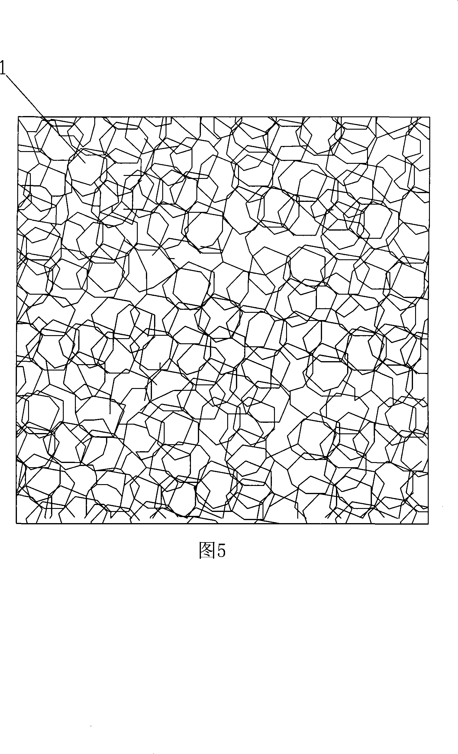
[0025] Please refer to FIG. 5 , which is a preferred embodiment of the heat dissipation capillary structure of the present invention. The heat dissipation capillary structure 1 is made of metal with better heat transfer performance, such as copper or aluminum. The heat dissipation capillary structure 1 is a three-dimensional network cross-linked structure, which has a three-dimensional shape compared with the network two-dimensional planar structure; compared with the sintered powder, it has a more complete network cross-linked structure and a larger Porosity; grea...


PUM


Abstract

The invention provides a heat dissipating capillary structure which is a metal capillary structure, and the metal capillary structure is a three-dimensional reticular cross-linkage structure. The heat dissipating capillary structure is the three-dimensional reticular cross-linkage structure which has the three-dimensional solid shape and complete reticular cross-linkage structure and larger gap rate and also has larger capillary force. The invention also provides a heat conducting component which uses the heat dissipating capillary structure and the method for manufacturing the heat dissipating capillary structure. The heat conducting component has good performance of heat conduction, and the method for manufacturing the heat dissipating capillary structure is simple.

Description

【Technical field】 [0001] The invention relates to a heat dissipation capillary structure, a heat transfer component using the heat dissipation capillary structure and a method for manufacturing the heat dissipation capillary structure 【Background technique】 [0002] With the continuous improvement of the power of electronic components such as CPUs, people pay more and more attention to the problem of heat dissipation. In the existing heat dissipation design, a large number of heat transfer components such as heat pipes, vapor chambers (radiating plates), and flat heat pipes are used. [0003] As shown in Figure 1, the commonly used design is to set a sealed cavity 1', and the sealed cavity 1' is provided with a liquid-absorbing core 2' and a working fluid 3'. Draw the inside of the sealed cavity 1' to 1.3×(10 -1 ~10 -4 )Pa negative pressure, then filled with an appropriate amount of working fluid 3', so that the capillary porous material of the liquid-absorbing core 2' clo...

Claims


Application Information

Patent Timeline
IPC IPC(8): H05K7/20H01L23/427
CPCH01L2924/0002
Inventor 艾建华
Owner 艾建华
Why Eureka
Try Eureka