Exhaust gas heat exchanger

An exhaust gas heat exchanger technology, which is applied in heat exchange equipment, exhaust gas recirculation, exhaust devices, etc., can solve the problem of reduced shear force on the surface of unburned matter at the flow rate of exhaust gas, decreased heat transfer rate, and aggravated accumulation of unburned matter And other issues

Inactive Publication Date: 2010-06-09
DENSO CORP
View PDF2 Cites 7 Cited by
  • Summary
  • Abstract
  • Description
  • Claims
  • Application Information

AI Technical Summary

Problems solved by technology

Therefore, a decrease in exhaust flow rate may result
Correspondingly, a decrease in exhaust gas flow rate may decrease the heat transfer rate
Also, the reduction in exhaust flow rate may reduce the surface shear forces that would otherwise blow off unburned material
As a result, disadvantageously, the accumulation of unburned substances on the wall may be exacerbated

Method used


Image

  • Exhaust gas heat exchanger
  • Exhaust gas heat exchanger
  • Exhaust gas heat exchanger

Examples


no. 1 example

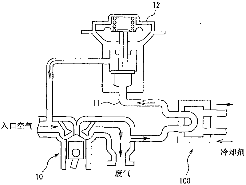
[0020] In the first embodiment, the exhaust gas heat exchanger of the present invention is applied to the EGR gas cooler 100 of the diesel engine 10 . figure 1 A schematic diagram of an EGR (Exhaust Gas Recirculation) system having an EGR gas cooler 100 according to the present embodiment is shown.

[0021] EGR is used to reduce nitrogen oxides in exhaust gas of a vehicle engine 10 (internal combustion engine), and includes an exhaust gas recirculation duct 11 , an EGR valve 12 and an EGR gas cooler 100 . The exhaust gas recirculation duct 11 returns a part of the exhaust gas discharged from the engine 10 to the upstream (or inlet side) of the engine 10 .

[0022] The EGR valve 12 is provided in the exhaust gas recirculation conduit 11 and adjusts the amount of exhaust gas (hereinafter referred to as EGR gas) flowing through the exhaust gas recirculation conduit 11 according to the operation of the engine 10 . The EGR gas cooler 100 is a heat exchanger that exchanges heat be...


PUM


Abstract

An exhaust gas heat exchanger for an internal combustion engine includes an exhaust passage and an offset fin. The offset fin includes a plurality of side walls and a plurality of top walls. The offset fin is defined into a plurality of segments that are offset from each other in an offset direction. One of the plurality of top walls of the offset fin has a projection that inwardly projects therefrom. The projection is provided to one of the plurality of segments. The projection of the one of the plurality of segments is opposed to an upstream end portion of the other one of the plurality of side walls of the other one of the plurality of segments that is positioned adjacently downstream of the one of the plurality of segments in the circulation direction.

Description

technical field [0001] The present invention relates to an exhaust gas heat exchanger for exchanging heat between (a) a cooling fluid and (b) exhaust gas discharged from an internal combustion engine. Background technique [0002] For example, a conventional exhaust gas heat exchanger is described in JP-A-2003-106785 (corresponding to EP1411315A1). For example, the exhaust gas heat exchanger of JP-A-2003-106785 has internal fins of the offset type, which are provided in an exhaust gas passage in a pipe through which the exhaust gas flows. The protrusion protrudes inwardly from the top wall of the inner fin, and the exhaust gas flows through the exhaust gas passage along a curved path (zigzag path) toward the opposite top wall. [0003] More specifically, the inner fins include segments that are offset from each other. For example, the segments are arranged along the flow direction of the exhaust gas and are placed alternately with each other in a direction perpendicular to...

Claims


Application Information

Patent Timeline
Patent Type & Authority Applications(China)
IPC IPC(8): F02M25/07F28F3/06
CPCY02T10/146F02M25/0737Y02T10/121F01N5/02Y02T10/16F02B29/0418F02M26/32Y02T10/12
Inventor 畔柳功林孝幸寺地翔太
Owner DENSO CORP
Why Eureka
Try Eureka