

Evaporative Fuel Treatment Unit
A technology for evaporative fuel and processing device, which is applied in the field of evaporative fuel processing device, and can solve the problems such as the reduction of the ability to remove evaporative fuel
- Summary
- Abstract
- Description
- Claims
- Application Information
AI Technical Summary
Problems solved by technology
Method used
Image

Examples
no. 1 example
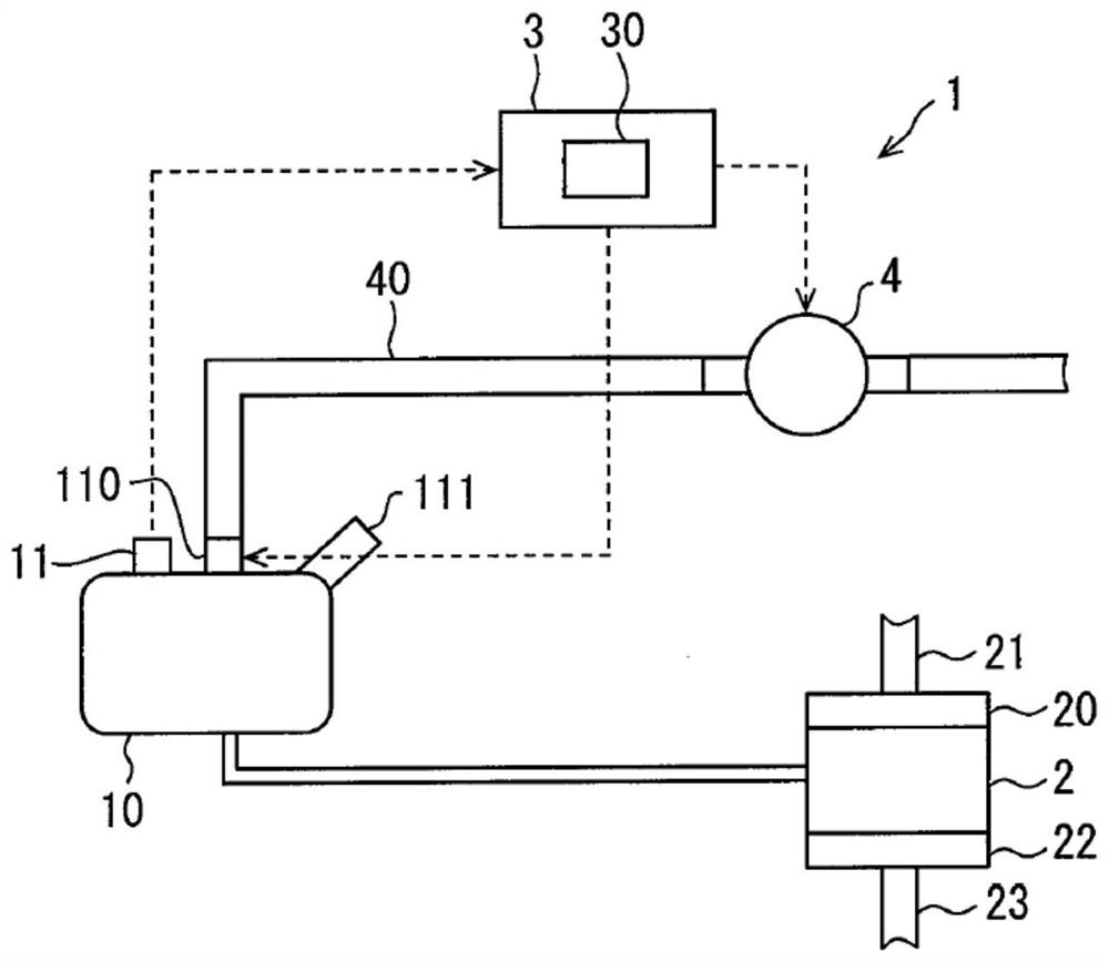
[0017] refer to Figure 1-Figure 4 , the evaporated fuel processing device 1 according to the first embodiment will be described. The evaporated fuel processing device 1 has the function of restricting fuel vapor generated by evaporation of the fuel in the fuel tank 10 and preventing the evaporated fuel from being discharged from the fuel tank 10 into the atmosphere.
[0018] Hereinafter, the evaporated fuel processing device 1 may be referred to as "device 1". The evaporated fuel processing device 1 includes a fuel tank 10 in which fuel to be burned in the internal combustion engine 2, such as gasoline, is stored. Fuel in the fuel tank 10 is supplied into the internal combustion engine 2 through an injector via a fuel supply passage connecting the fuel tank 10 and the internal combustion engine 2 . The supplied fuel is mixed with intake air for combustion in a combustion chamber of the internal combustion engine 2 . The internal combustion engine 2 is connected to an intak...
no. 2 example
[0042] will refer to Figure 5 and Figure 6 The evaporated fuel processing device 101 of the second embodiment will be described. Hereinafter, the evaporated fuel processing device 101 may also be referred to as "device 101". The difference between the device 101 and the device 1 of the first embodiment is that the device 101 includes a canister 13 into which evaporated fuel generated in the fuel tank 10 can be adsorbed. Therefore, in the device 101 , evaporated fuel in the fuel tank 10 passes through the on-off valve 110 in an open state, and then flows out to the passage 40 . Subsequently, evaporated fuel flows into and is adsorbed into the tank 13 . The device 101 has a function of returning evaporated fuel adsorbed in the tank 13 to the inside of the fuel tank 10 . The structures, actions and effects not described in the second embodiment are similar to those of the first embodiment. Only points of difference from the first embodiment are described below.
[0043] T...
no. 3 example
[0049] refer to Figure 7 The evaporated fuel processing device 201 of the third embodiment will be described. Hereinafter, the evaporated fuel processing device 201 may also be referred to as "device 201". The device 201 is different from the first embodiment in that HC (hydrocarbon) gas contained in the fuel adsorbed to the canister 13 is supplied to the intake passage of the internal combustion engine 2 . The pressurization process performed by the pump 4 in the evaporative fuel restriction control of the first embodiment is performed by the purge pump 14 in the device 201. Therefore, the purge pump 14 forms an example of a pressurizing portion that increases the internal pressure TP of the fuel tank 10 by supplying gas to the inside of the fuel tank 10 . Such as Figure 7 As shown, the device 201 includes an evaporated fuel removal system and an intake system of the internal combustion engine 2 , the intake system forms an intake passage of the internal combustion engin...
PUM
 Abstract
Description
Claims
Application Information