Radiating structure

A technology of heat dissipation structure and return zone, applied in indirect heat exchangers, lighting and heating equipment, etc., can solve the problems of heat conduction failure, accumulated heat, and the inability of working fluid to return, so as to prevent heat leakage and improve heat transfer effect. Effect

Active Publication Date: 2014-08-06
ASIA VITAL COMPONENTS SHENZHEN CO LTD
View PDF5 Cites 5 Cited by
  • Summary
  • Abstract
  • Description
  • Claims
  • Application Information

AI Technical Summary

Problems solved by technology

[0005] The vapor chamber is a kind of vertical heat conduction between surfaces, so the heat is mainly transferred from one side plane to the other side plane. It has the advantages of large area heat conduction and fast heat conduction speed, but its disadvantage is that it cannot The heat is transferred to the remote side for heat dissipation. If the heat cannot be dissipated in a timely manner, it is easy to accumulate heat near the heat source. Therefore, this shortcoming is still the biggest shortcoming of the vapor chamber
[0006] Furthermore, in order to achieve a thinner vapor chamber, the loop heat pipe technology is applied to the vapor chamber, mainly by setting up micro-channels on the corresponding sides of the two thin copper plates to form an evaporation zone and a condensation zone And the return area is filled with working fluid, so as to form a vapor-liquid cycle, and the loop heat pipe is the most common problem of heat leakage, so this problem is more likely to occur in a relatively narrow flow channel, which is likely to cause condensation after condensation The working fluid cannot return to the evaporation area, so that the vapor-liquid circulation of the working fluid inside the vapor chamber is suspended, and the overall heat conduction fails

Method used


Image

  • Radiating structure
  • Radiating structure
  • Radiating structure

Examples


Embodiment Construction

[0030] The above-mentioned purpose of the present invention and its structural and functional characteristics will be described according to the preferred embodiments of the accompanying drawings.

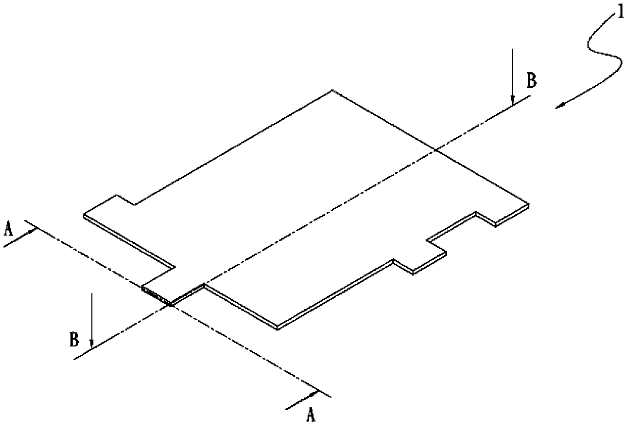
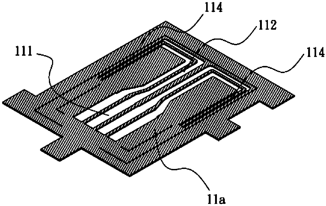
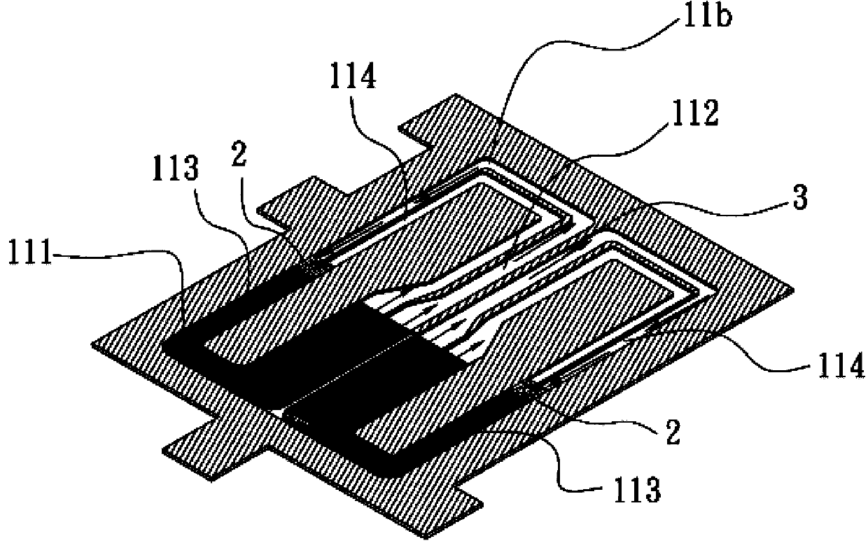
[0031] see figure 1 , figure 2 , image 3 , Figure 4 , is a perspective view and A-A and B-B cross-sectional views of the first embodiment of the heat dissipation structure of the present invention, as shown in the figure, the heat dissipation structure of this embodiment includes: a body 1;

[0032] The body 1 has a chamber 11, the chamber 11 has an evaporation zone 111 and a condensation zone 112 and a first recirculation zone 113 and a second reflow zone 114, the evaporation zone 111 and the condensation zone 112 and The first and second recirculation regions 113 and 114 communicate with each other, and a heat-insulating coating 2 is coated on the intersection of the first and second recirculation regions 113 and 114 , and the chamber 11 is filled with a working fluid 3 . ...


PUM


Abstract

The invention discloses a radiating structure which comprises a body. The body is provided with a chamber, the chamber is provided with an evaporation zone, a condensation zone, a first backflow zone and a second backflow zone, the evaporation zone is communicated with the condensation zone, the first backflow zone and the second backflow zone, a heat-insulation plating covers an intersection of the first backflow zone and the second backflow zone, and the chamber is filled with working liquid. The radiating structure has the advantages that heat leakage in a space between the evaporation zone and the condensation zone can be prevented owing to the heat-insulation plating, and accordingly vapor and liquid in the radiating structure can keep smoothly circulating.

Description

technical field [0001] A heat dissipation structure, especially a heat dissipation structure that can prevent heat leakage inside the heat dissipation structure and further stabilize the internal vapor-liquid circulation. Background technique [0002] As the current electronic equipment is gradually advertised as light and thin, the size of each component must be reduced accordingly. However, the heat generated by the reduction in the size of electronic equipment has become a major obstacle to the improvement of the performance of electronic equipment and systems. Despite the ever-shrinking dimensions of the semiconductors forming electronic components, there is a continuing demand for increased performance. [0003] As semiconductors shrink in size, the resulting heat flux increases. The heat flux increase creates challenges in cooling the product beyond just the overall heat increase, because the heat flux increase causes overheating at different times and at different len...

Claims


Application Information

Patent Timeline
Patent Type & Authority Applications(China)
IPC IPC(8): F28D15/02
Inventor 杨修维
Owner ASIA VITAL COMPONENTS SHENZHEN CO LTD
Why Eureka
Try Eureka