Die cushion drive system

A buffer mechanism and drive device technology, applied in the direction of output power conversion devices, presses, manufacturing tools, etc., can solve problems such as energy consumption, and achieve the effect of miniaturization and low price

Active Publication Date: 2008-01-30
FANUC LTD
View PDF2 Cites 0 Cited by
  • Summary
  • Abstract
  • Description
  • Claims
  • Application Information

AI Technical Summary

Problems solved by technology

[0005] As far as the above-mentioned existing hydraulic die cushioning mechanism driving method is concerned, when the force from the slider 51 to the die cushioning mechanism 52 exceeds the force from the die cushioning mechanism 52 to the slider 51, the energy will flow in the direction of the thick arrow in the figure. transfer, as heat is released from the hydraulic device 58, thereby creating the problem of inefficient consumption of energy

Method used


Image

  • Die cushion drive system
  • Die cushion drive system
  • Die cushion drive system

Examples


Embodiment Construction

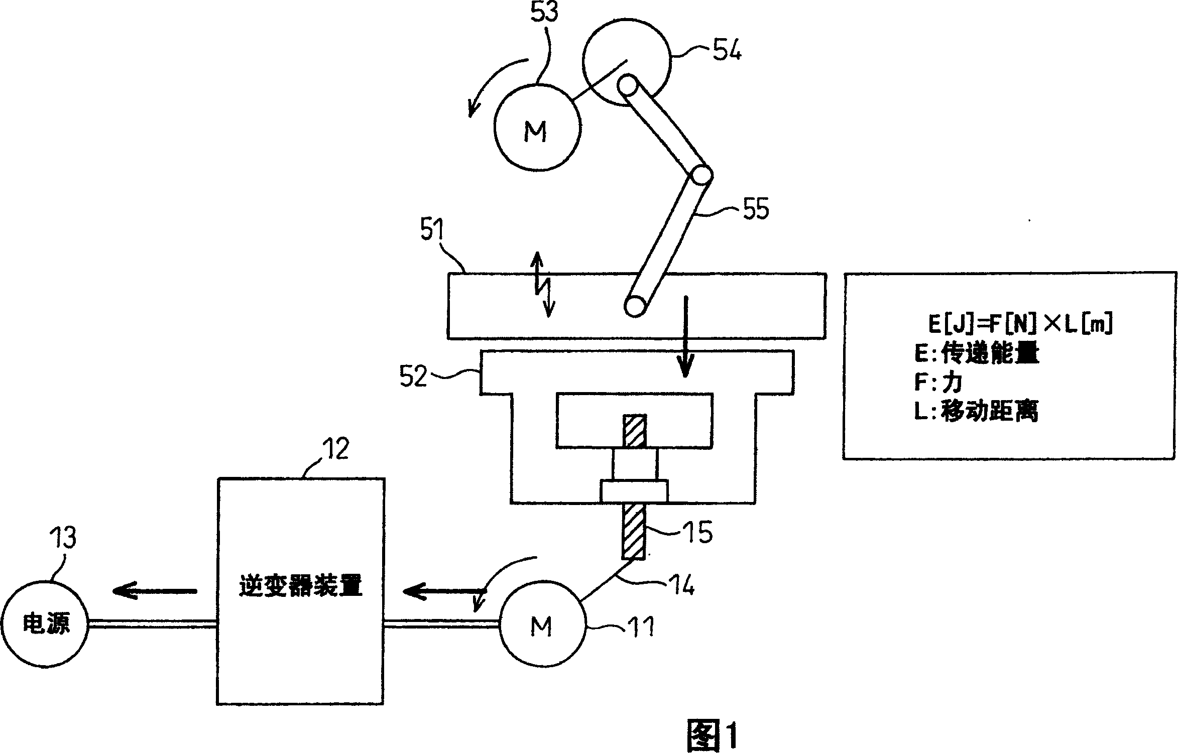
[0023] FIG. 1 is a side view showing the configuration of a die cushion mechanism driving device of a press machine according to an embodiment of the present invention. In this figure, the same reference numerals are assigned to the same parts as the conventional configuration shown in FIG. 5 , and description thereof will be omitted here. In this embodiment, there are provided: a servo motor 11 for driving the mold buffer mechanism 52; an inverter device 12 for supplying AC power to the servo motor 11; phase AC power supply 13 . The rotational energy of the servo motor 11 is given to the shaft 15 of the die cushion mechanism 52 as vertical motion energy through the ball screw 14 .

[0024] During power running, the slider 51 moves downward by the energy from the motor 53, and the inverter device 12 converts the AC power from the three-phase AC power supply 13 into AC power with the frequency and amplitude most suitable for driving the servo motor 11. By driving the servo mo...


PUM


Abstract

A die cushion drive system (1) provided with a servo motor (11), serving as a source of drive power for a die cushion (52) of a press machine and a power circuit (12) with a regeneration function which regenerates energy from the servo motor (11) and returns it to an AC power supply (13), whereby it is possible to power the die cushion drive system (1) by a servo motor and return the regenerated energy of this servo motor to the power source so as to save on energy.

Description

technical field [0001] The invention relates to a driving device of a mold buffer mechanism of a stamping machine, in particular to a driving device of a mold buffer mechanism powered by a servo motor. Background technique [0002] The drive source of the die cushion mechanism of the conventional press machine is hydraulic pressure. [0003] Fig. 5 is a side view showing the configuration of a drive device for a die cushion mechanism of a conventional press machine. In this figure, 51 is a slider that moves up and down to press down a workpiece (not shown) such as a sheet metal, 52 is a die cushion mechanism that applies pressure upward to the workpiece, and 53 is a drive slider. 51 is the motor, 54 is the mechanism that converts the rotational energy of the motor into the energy of the up and down movement, 55 is the arm that gives the energy of the up and down movement to the slider 51, 56 is the hydraulic cylinder, 57 is the hydraulic conduit, and 58 is the hydraulic dev...

Claims


Application Information

Patent Timeline
Patent Type & Authority Patents(China)
IPC IPC(8): B21D24/02B30B15/02H02M5/257H02M7/48
CPCB21D24/02
Inventor 松原俊介堀越真一冈本敬山田裕一
Owner FANUC LTD
Why Eureka
Try Eureka