Inverter device for driving electric motor

A technology for inverters and motors, which is applied to electrical devices, AC motor control, electric vehicles, etc. It can solve problems such as inability to switch, poor operation, and changes in the operation status of electric fans and pumps, so as to achieve maintenance and improve operation reliability. sexual effect

Active Publication Date: 2009-07-01
FUJI ELECTRIC CO LTD +1
View PDF6 Cites 0 Cited by
  • Summary
  • Abstract
  • Description
  • Claims
  • Application Information

AI Technical Summary

Problems solved by technology

[0009] exist Image 6 In the shown conventional inverter device 2 for driving a motor, since only one set of general-purpose inverters 21 is provided, if any failure occurs in the inverter, it becomes the one for supplying the electric motor 3 with the electric power of the AC power source 1. state, as described above, there is a danger of changing the operating state of the motor load electric fan and pump
Moreover, after the general-purpose inverter 21 has been operated normally for a long time (for example, several years or more), if any failure occurs in the general-purpose inverter 21, when switching to the power supply from the AC power supply 1, There is a danger that the power supply from the AC power supply 1 cannot be switched due to malfunction due to welding of the contacts of the electromagnetic contactors 22 and 23, etc.
[0010] Moreover, as disclosed in the above-mentioned Patent Document 1, in a structure in which two sets of inverters, induction motors, and pumps are alternately operated for one water supply system, a larger installation space is required, and there are disadvantages of the device. The problem of higher overall prices

Method used


Image

  • Inverter device for driving electric motor
  • Inverter device for driving electric motor
  • Inverter device for driving electric motor

Examples


Embodiment Construction

[0024] Hereinafter, the present invention will be described with reference to illustrated examples.

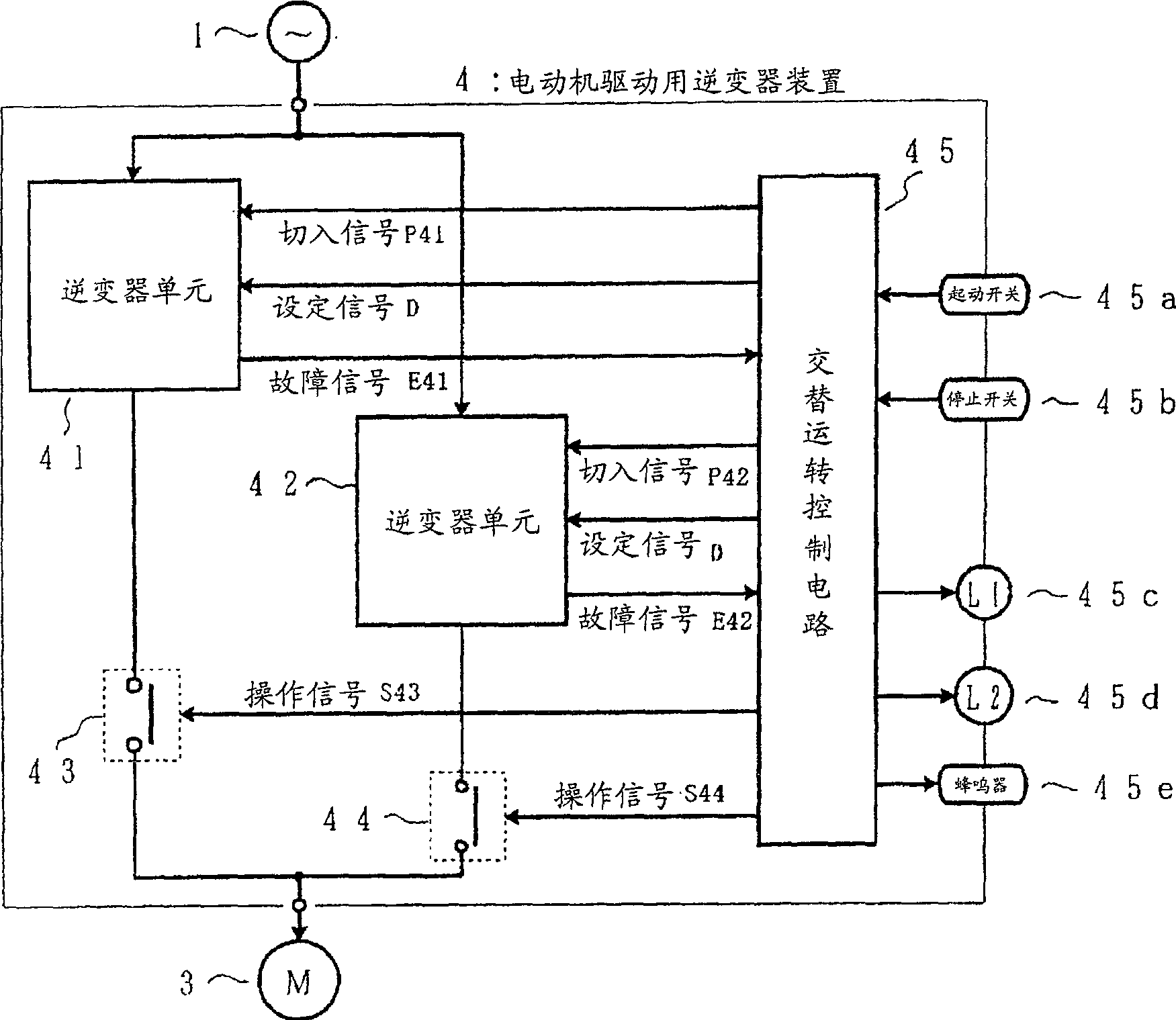
[0025] figure 1 It is a circuit configuration diagram showing a first embodiment of the inverter device for driving a motor according to the present invention. pair with Figure 6 The same functional elements as the structural elements of the shown conventional example are given the same reference numerals.

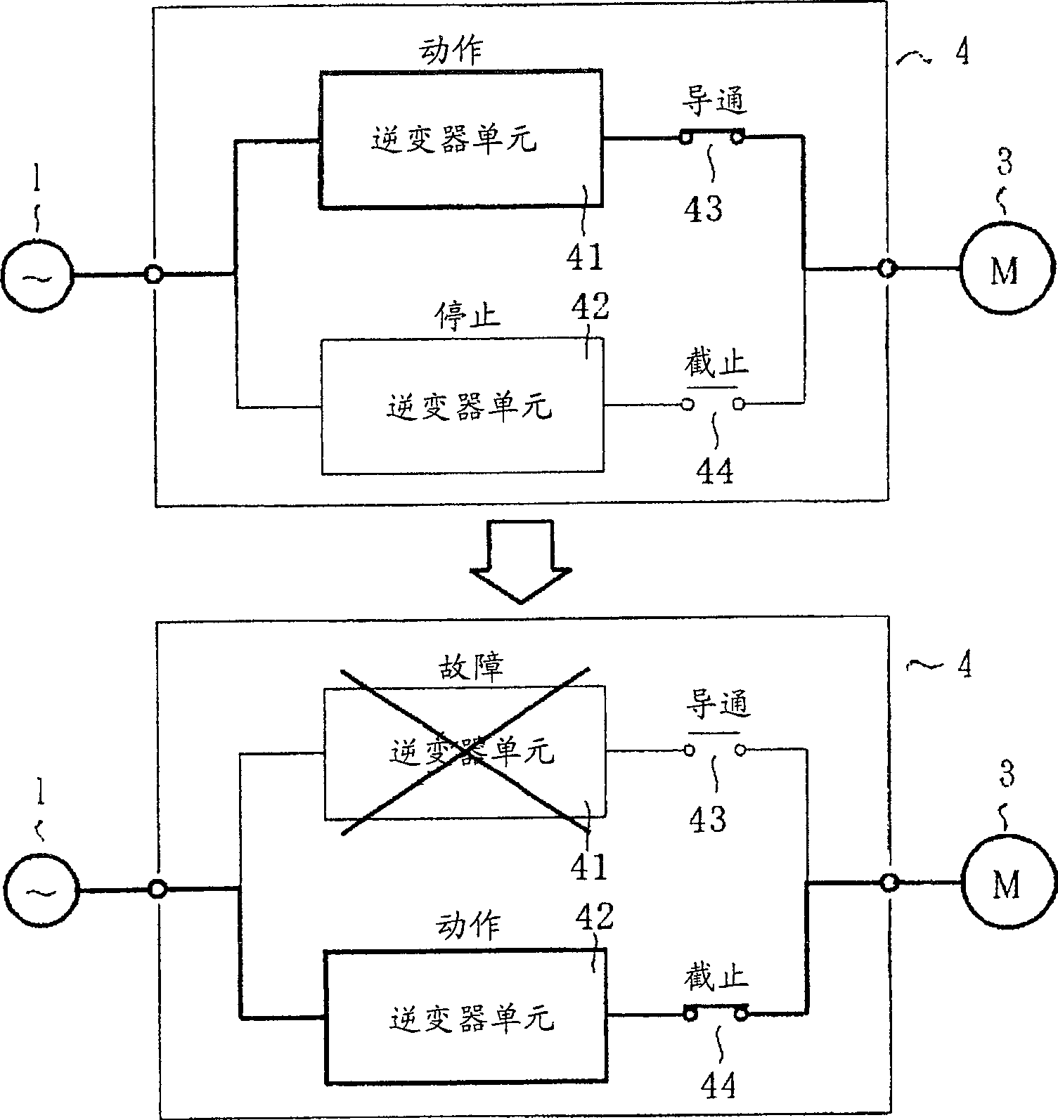
[0026] which is, figure 1 The shown inverter device 4 for driving a motor has two sets of inverter units 41 and 42 that are completely unitized like a general-purpose inverter and can independently generate AC power of variable voltage and variable frequency. A set of electromagnetic contactors 43, 44, and a set of alternate operation control circuits 45. The purpose of providing the electromagnetic contactors 43 and 44 is to switch between the motor 3 and the inverter by turning on the side connected to the operating inverter unit and turning off the side connected ...


PUM


Abstract

[PROBLEMS] An inverter for electric motor drive, suitable for an electric motor for fans and pumps and for en electric motor for driving motor vehicles. [MEANS FOR SOLVING PROBLEMS] An inverter device (4) for electric motor drive is constituted of two inverters, or an inverter (1) and an inverter (2), two electromagnetic contactors (43, 44), and one alternate operation control circuit (45). Usually, the inverter (1), the electromagnetic contactor (43) and the inverter (2), and the electromagnetic contactor (44) are alternately operated according to a command from the alternate operation control circuit (45) every time when a start switch (45a) and a stop switch (45b) are depressed, or alternatively, their operations are automatically alternated every 24 hours. As a result, their operation time periods are almost equal to each other, increasing operation reliability of the entire inverter device (5) and enabling power supply to an electric motor (3) to be continued even if either one fails.

Description

technical field [0001] The invention relates to an inverter device for driving a motor. The device generates AC power with variable voltage and frequency, and drives a motor with variable speed through the AC power, especially a motor that drives electric fans, pumps and the like. Background technique [0002] Figure 6 It is a circuit configuration diagram showing a conventional example of such an inverter device. In this figure, 1 is an AC power source such as a commercial power supply, 2 is an inverter device for driving a motor, and 3 is a motor such as an induction motor driven at a variable speed by the inverter device 2 for driving the motor. [0003] The inverter device 2 for driving a motor is composed of the following parts: the commercial power of a constant voltage and a constant frequency of the AC power supply 1 is converted into a ratio (V / f) of an output voltage V and a frequency f thereof which can be kept substantially constant. A general-purpose inverter ...

Claims


Application Information

Patent Timeline
Patent Type & Authority Patents(China)
IPC IPC(8): H02M7/48B60L3/00H02M7/493H02P27/06
CPCB60L3/0023B60H1/00885B60H1/00428Y02T10/88
Inventor 水口雄二朗石井新一山下理人青山敏也
Owner FUJI ELECTRIC CO LTD
Why Eureka
Try Eureka