
Full automatic sprayer

A sprayer, fully automatic technology, applied in the direction of injection device, liquid injection device, etc., can solve the problems of cumbersome operation and high labor intensity, and achieve the effect of easy operation

Inactive Publication Date: 2008-02-06
池龙岩 +1
View PDF9 Cites 0 Cited by
  • Summary
  • Abstract
  • Description
  • Claims
  • Application Information

AI Technical Summary

Problems solved by technology

[0003] The purpose of the present invention is to solve the problems of cumbersome operation and high labor intensity when the existing sprayer needs to be moved up and down to squeeze the pressure handle during use, and to provide a full-automatic sprayer that can overcome the above-mentioned shortcomings.

Method used


Image

  • Full automatic sprayer
  • Full automatic sprayer
  • Full automatic sprayer

Examples


Embodiment Construction

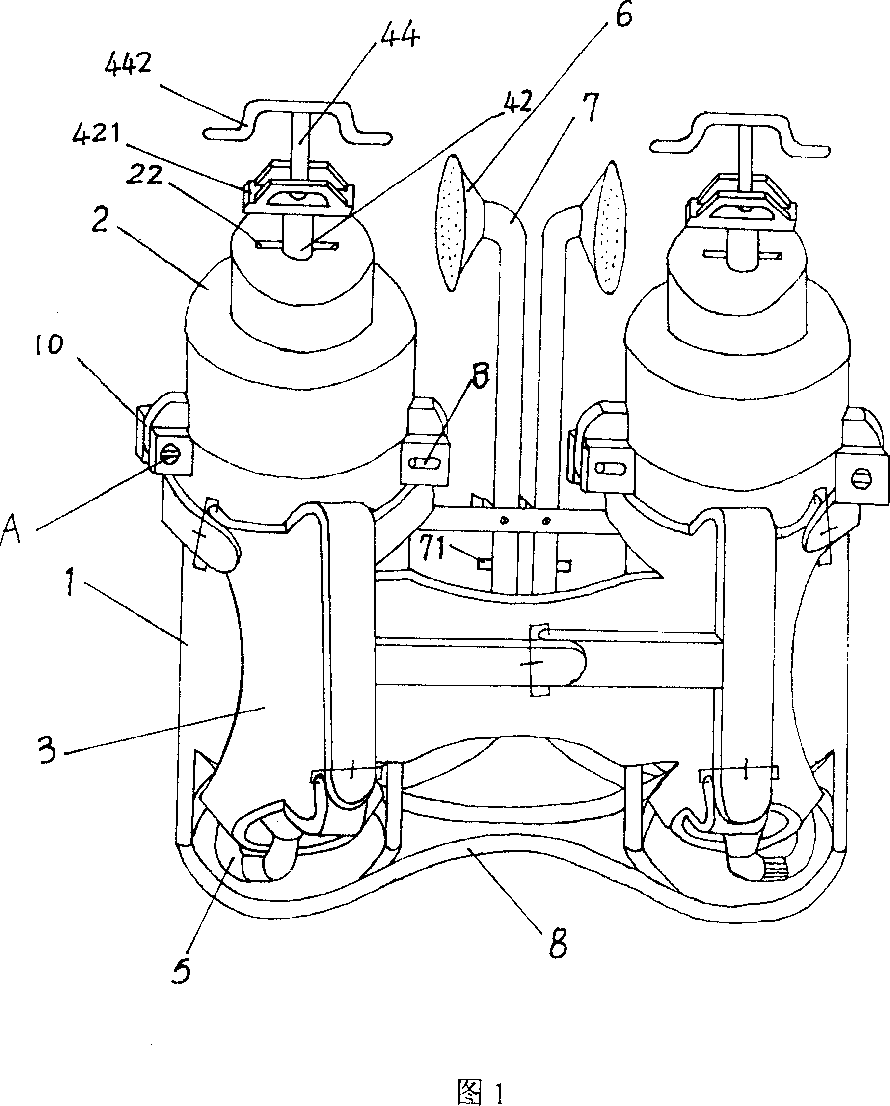
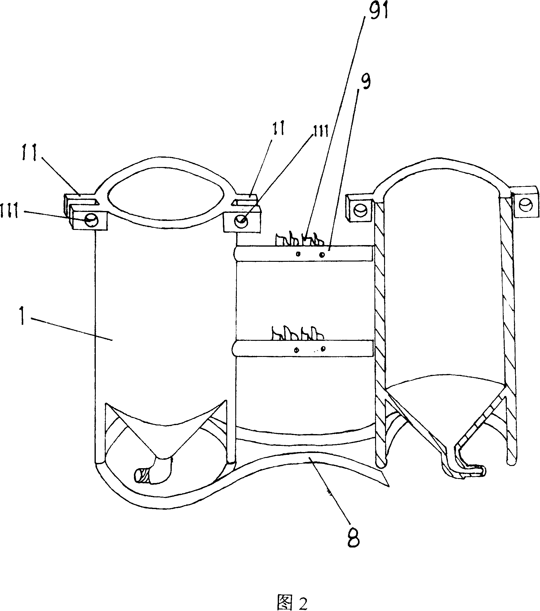
[0013] Please refer to Fig. 1 and shown in Fig. 2, the present invention can be used alone, and can also be used when two are connected together. When the two are connected together for use, a conjoined base 8 is provided, and two barrels 1 are placed on the conjoined base. 8, the strap 3 is a conjoined strap, and a nozzle placement rod 9 is arranged between the two barrels 1, and a clip 91 for clamping the nozzle 6 is arranged on the nozzle placement rod 9.

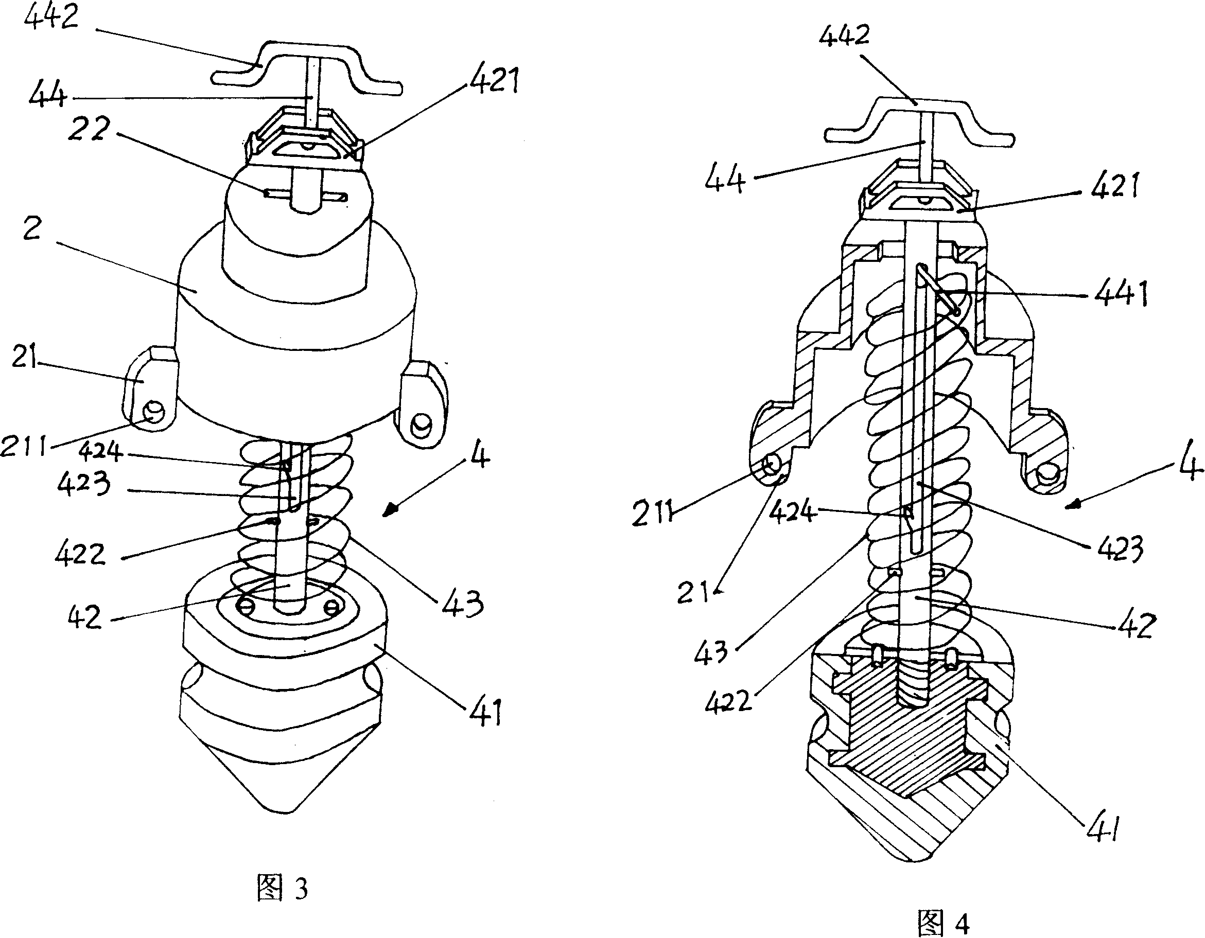
[0014] Please refer to Fig. 1, Fig. 2, Fig. 3, and Fig. 4, the present invention includes a barrel body 1, a cover 2, a strap 3, a pressurizing device 4, a liquid outlet pipe 5, a spray rod 7 and a nozzle 6, wherein, The pressurizing device 4 is arranged in the barrel body 1, the strap 3 is fixed outside the barrel body 1, one end of the liquid outlet pipe 5 is connected with the bottom of the barrel body 1, and the other end of the liquid outlet pipe 5 is connected with the nozzle 6 through the spray rod 7 , the spray r...


PUM


Abstract

A full-automatic spraying machine is composed of cylindrical bodies, sealing covers, braces, pressurizing units, liquid outlet tubes, spray tubes and nozzles. Said presurizing unit consists of pressurizing piston and its raising rod, pressing spring, and secondary pressurizing rod with a handle.

Description

technical field [0001] The invention relates to a sprayer, in particular to a full-automatic sprayer. Background technique [0002] At present, there are two types of sprayers used in the market, large and medium-sized, which are electric squeeze type and hand-operated squeeze type with the back of the body. Yes, there is a drug injection port on the upper part of the oblate barrel, the drug injection port is covered with a barrel cover, and a spray rod is inserted on the side of the oblate barrel. At the same time, there is also an up and down squeezing air barrel, which rushes air into the high-pressure bag, so that the air can squeeze the liquid medicine to the spray nozzle of the spray bar and spray it out. The disadvantage of the sprayer with this structure is that it needs to reciprocate up and down to squeeze the punching pressure handle during use, which is cumbersome to operate and labor-intensive to operate manually. Contents of the invention [0003] The purpo...

Claims


Application Information

Patent Timeline
Patent Type & Authority Patents(China)
IPC IPC(8): B05B9/03
Inventor 池龙岩李国强
Owner 池龙岩
Learn More