
Concealed earphone detector and detection method thereof

An invisible earphone and detector technology, applied in electromagnetic wave detection and other directions, can solve the problems of high signal strength, limited sensitivity, human injury, etc., and achieve the effect of simplifying inspection steps, high detection accuracy and saving time.

Inactive Publication Date: 2008-02-13
凌子龙
View PDF4 Cites 0 Cited by
  • Summary
  • Abstract
  • Description
  • Claims
  • Application Information

AI Technical Summary

Problems solved by technology

This method can only make the mobile phone in the place have no signal and cannot talk. If the user chooses other equipment instead of the mobile phone, it will not be affected in any way, and it is far from reaching the purpose of eliminating the use of invisible earphones.
In addition, the mobile phone signal jammer has the following disadvantages: first, it may affect the use of normal mobile phones around the place, causing unnecessary trouble; moreover, its signal strength is too large, which may cause certain harm to the human body; high cost problem
This method requires a full-body inspection of the inspected object, which is very slow and difficult to grasp the sensitivity. The inspected object will inevitably have metal objects such as belt buckles, keys, hairpins, zippers, etc., which can easily cause false alarms. In addition, due to its Sensitivity is limited, so tiny devices on the subject may still not be detected, and even tiny earphones in the subject's ear canal may not be detected
There is no guarantee that 100% will eliminate the illegal use of invisible earphones
[0007] Since the above-mentioned detection methods have limitations and have their own problems, it is urgent to develop a new detection method and equipment to prevent the abuse of invisible earphones

Method used


Image

  • Concealed earphone detector and detection method thereof
  • Concealed earphone detector and detection method thereof
  • Concealed earphone detector and detection method thereof

Examples


Embodiment Construction

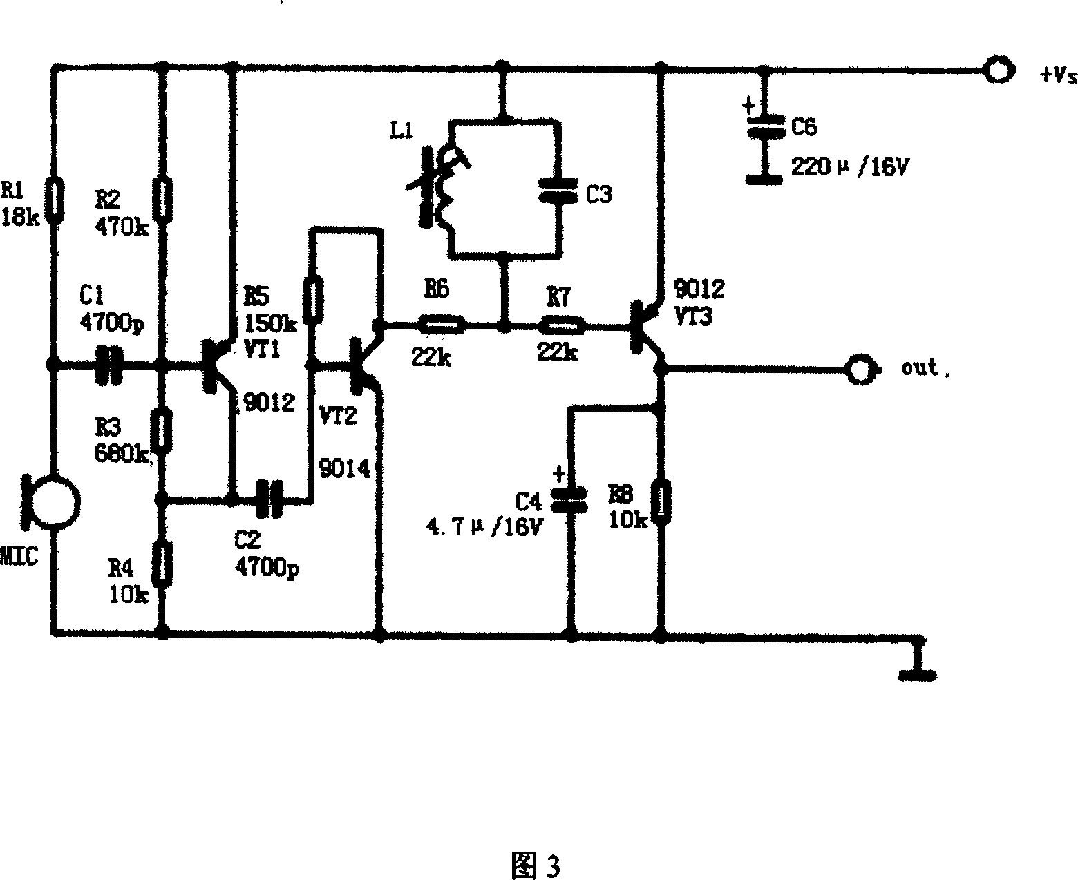
[0051] The invisible earphone detector working under the control of the main control circuit of the present invention will be described in further detail below in conjunction with the accompanying drawings. The main control circuit can use the AT89C51 single-chip microcomputer as the core component, and of course other types of single-chip microcomputers can also be used as the core component. Because the control mode adopted by the detector of the present invention is not complicated, it can also be made into a simpler detection device without smart chips such as single-chip microcomputers.

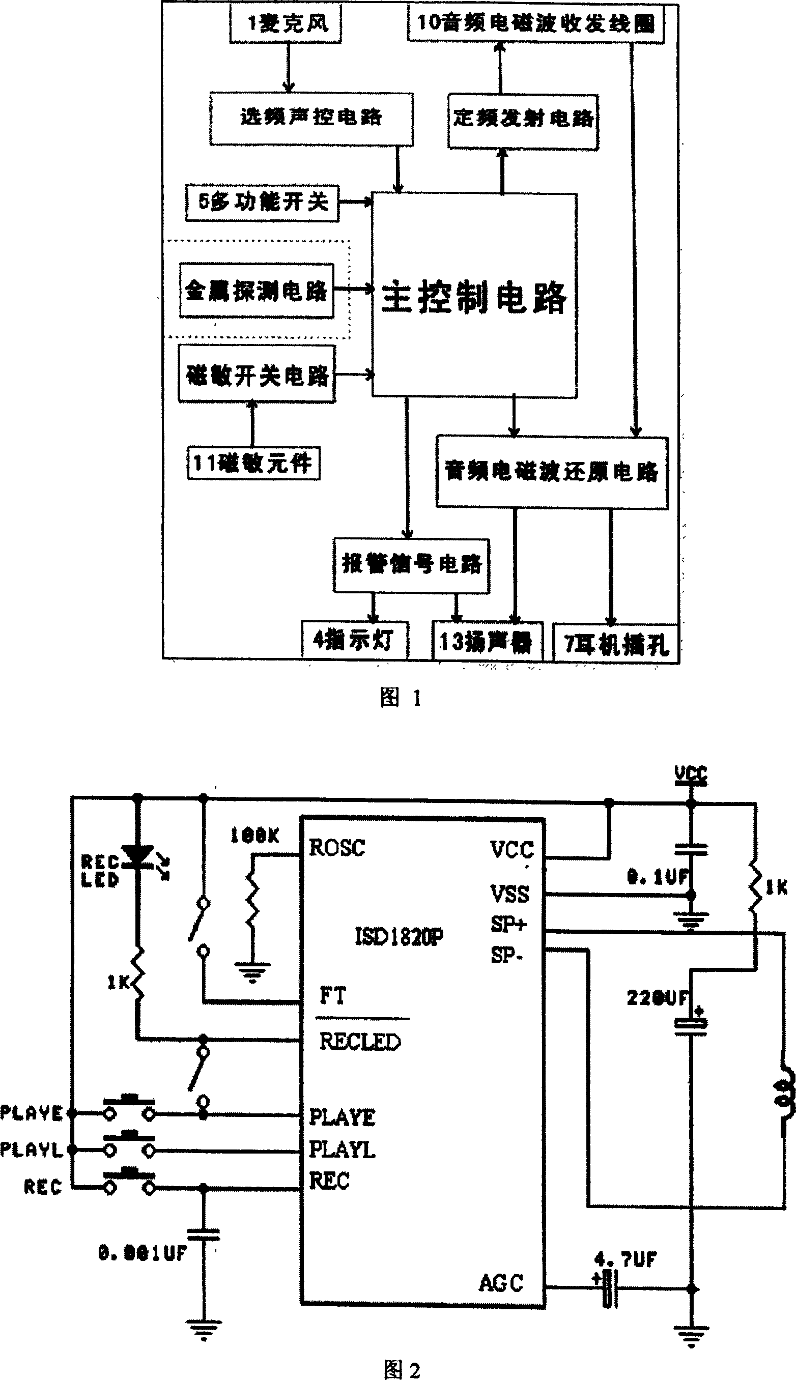
[0052] Fig. 1 is the structural block diagram of invisible earphone detector of the present invention, is used for detecting whether the person under inspection wears the parts of electronic class earphone, consists of main control circuit, fixed frequency transmission circuit, audio frequency electromagnetic wave transceiver coil 10, microphone 1, frequency selection sound control circui...


PUM


Abstract

The invention discloses a stealth earphone detector and detecting method, which comprises the following parts: AF electromagnetic emission part, fixed-rate emission circuit, acoustic wave receiving part, frequency-selective acoustic control circuit and main control circuit, wherein the main control circuit controls one or more acoustic frequency electric signal from fixed-rate emission circuit, which drives acoustic electromagnetic wave to send and receive acoustic electromagnetic wave of coil; the electromagnetic wave can be reduced into same-frequency sound by electronic stealth earphone within certain scale; when the microphone picks up sound to excite the frequency-selective acoustic control circuit, the main control circuit judges according to input electric signal of frequency-selective acoustic control circuit due to certain degree acoustic radiation from earphone outsides for electronic stealth earphone.

Description

technical field [0001] The invention relates to a non-contact detection device, in particular to a non-contact detection device for invisible earphones. Background technique [0002] There is a new type of invisible communication tool in the society-invisible earphones (the volume is very small, only a few millimeters, and it is difficult to observe with the naked eye when it is placed in the ear canal). Invisible earphones mainly include rare earth type and electronic type: rare earth type invisible earphones mainly rely on the induction vibration of strong magnetic materials (mainly NdFeB magnets) in the audio magnetic field to vibrate the ear canal so that the wearer can hear the sound; electronic earphones are It is more precise and does not contain large strong magnets. It mainly relies on the induced electromotive force obtained by the induction coil in the audio magnetic field to actively drive the magnetic horn to sound. The systems that provide the audio magnetic f...

Claims


Application Information

Patent Timeline
Patent Type & Authority Patents(China)
IPC IPC(8): G01V3/12
Inventor 凌子龙
Owner 凌子龙
Learn More