Mixed excitation switch reluctance motor

A technology of switched reluctance motor and mixed excitation, which is applied in the direction of electrical components, electromechanical devices, magnetic circuit static parts, etc., and can solve the problems of low performance-to-volume ratio

Inactive Publication Date: 2008-02-13
HARBIN INST OF TECH
View PDF2 Cites 1 Cited by
  • Summary
  • Abstract
  • Description
  • Claims
  • Application Information

AI Technical Summary

Problems solved by technology

The invention can solve the disadvantage of low performance volume ratio of existing switched reluctance motors

Method used


Image

  • Mixed excitation switch reluctance motor

Examples


specific Embodiment approach 1

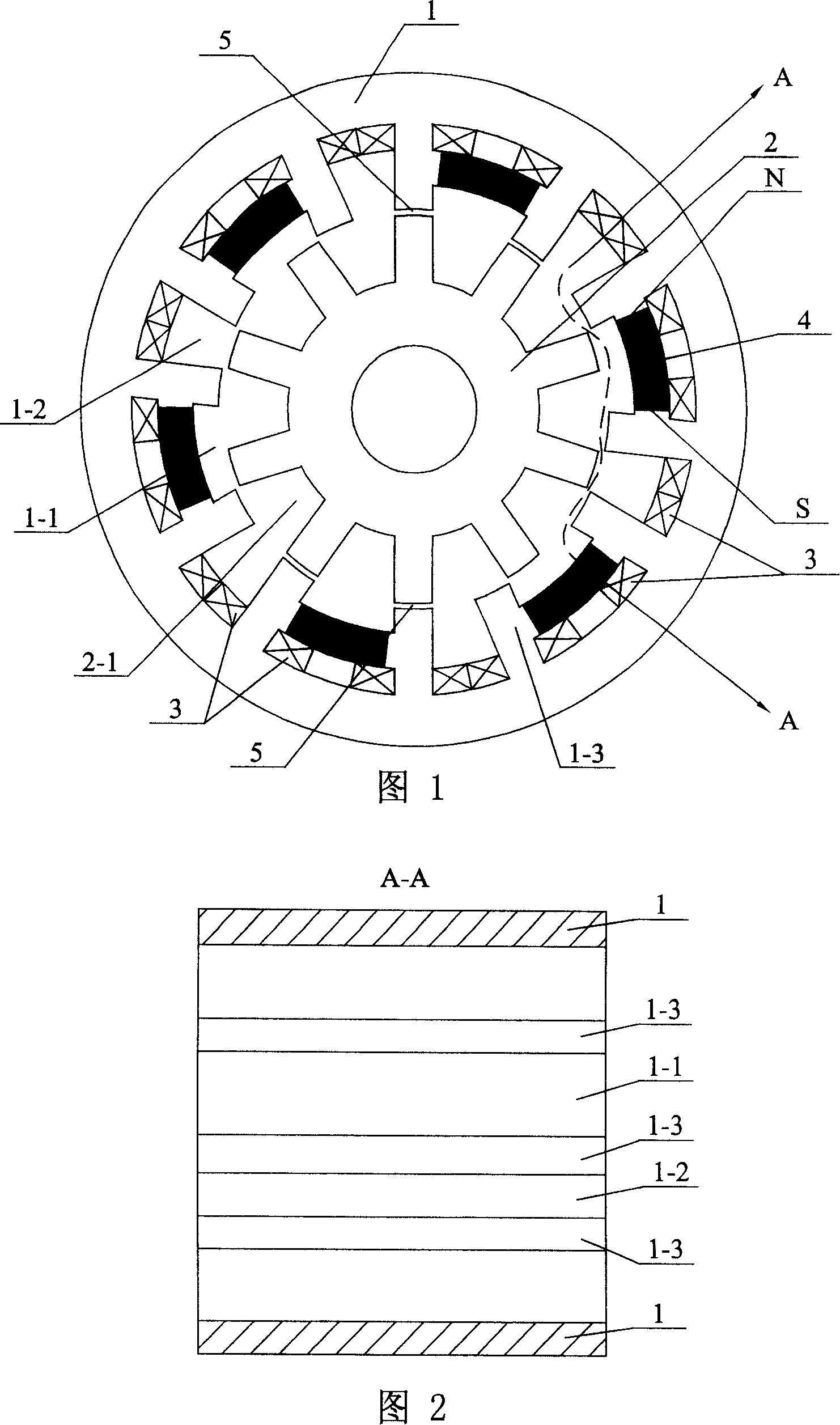
[0005] Specific embodiment 1: This embodiment is described in conjunction with Fig. 1 and Fig. 2. This specific embodiment consists of a stator 1, a rotor 2, an excitation winding 3, and a permanent magnet 4; the stator 1 is a cylindrical sleeve made of a magnetically conductive material, and the inner There are a plurality of wide slots 1-1 and narrow slots 1-2 on the cylindrical surface, the length direction of the wide slots 1-1 and narrow slots 1-2 is parallel to the axis line of the stator 1 and runs through the inner cylindrical surface of the stator 1, The wide slots 1-1 and the narrow slots 1-2 are evenly spaced from each other, and the thickness of the pole body 1-3 between the wide slots 1-1 and the narrow slots 1-2 is equal; the rotor 2 is a cylinder made of magnetically conductive material A plurality of slots 2-1 are evenly opened on the outer cylindrical surface of the rotor 2, and the length direction of the slots 2-1 is parallel to the rotation axis of the rotor...

specific Embodiment approach 2

[0006] Embodiment 2: In this embodiment, the stator 1 is made of superimposed silicon steel sheets, and the rotor 2 is made of superimposed silicon steel sheets. Other compositions and connections are the same as in the first embodiment.

specific Embodiment approach 3

[0007] Embodiment 3: The direction of the magnetic force lines generated by the excitation winding 3 in this specific embodiment is consistent with the direction of the magnetic force lines of the permanent magnet 4 . Other compositions and connections are the same as in the first embodiment.


PUM


Abstract

A composite excitation switch magnetic resistance motor is composed of a stator, a rotor, an excitation winding and a permanent magnet among which, the magnet is inserted in each wide slot, N and S poles of which are connected on two vertical walls of the slot, an excited winding is winded on the root of each pole body of the stator sleeved on the rotor with an air gap between surfaces of the stator internal post and the rotor outer post and the stator axial lead is coincident with that of the rotor.

Description

Technical field: [0001] The invention relates to a switching motor, in particular to a switched reluctance motor with mixed excitation of electromagnetic and permanent magnet. Background technique: [0002] Both the stator and the rotor of the existing switched reluctance motor have a salient pole structure. By sequentially energizing the stator field windings, the electromagnetic force interaction between the stator poles and the rotor poles produces torque. Since there are only excitation windings on the stator and no permanent magnets, and no windings and permanent magnets on the rotor, the structure of the motor is simple and the operation is reliable. But precisely because neither the stator nor the rotor uses permanent magnets, in order to obtain a large output torque, a motor with a larger volume must be used, and at the same time a large excitation power is required, which limits the performance-to-volume ratio of the motor and increases the cost of the drive syste...

Claims


Application Information

Patent Timeline
Patent Type & Authority Patents(China)
IPC IPC(8): H02K37/00H02K37/04H02K1/17H02K1/22
Inventor 寇宝泉李立毅程树康李小鹏
Owner HARBIN INST OF TECH
Why Eureka
Try Eureka