Supercharge Your Innovation With Domain-Expert AI Agents!

Light conducting plate and back light module

A technology of backlight module and light guide plate, applied in the directions of light guide, optics, optical components, etc., can solve the problems of high cost, disadvantageous precision machining, difficult multi-layer structure processing, etc., and achieve the effect of simplifying the system and improving performance.

Active Publication Date: 2008-02-20
TSINGHUA UNIV +1
View PDF10 Cites 1 Cited by
  • Summary
  • Abstract
  • Description
  • Claims
  • Application Information

AI Technical Summary

Problems solved by technology

However, the height (depth) of the V-shaped bump 42 increases from the center to both sides. This structure is not conducive to precision machining; and the light guide plate of this structure has no angle control function, so it is necessary to add a multi-layer optical film. so that the final outgoing light can be emitted vertically
[0012] As shown in Figure 5, US Patent No. 5,237,641 published on August 17, 1993 discloses a backlight module capable of controlling the angle of outgoing light, which includes a side light source 51 and a light guide plate 52, the light guide plate 52 reflects A multilayer structure is arranged on the surface, and the outermost layer has a V-shaped microstructure 54, but the multilayer structure is difficult to process and high in cost, which is not conducive to application in large-size liquid crystal displays

Method used


Image

  • Light conducting plate and back light module
  • Light conducting plate and back light module
  • Light conducting plate and back light module

Examples


Embodiment Construction

[0033] The light guide plate and the backlight module of the present invention will be further described in detail with reference to the accompanying drawings and multiple embodiments.

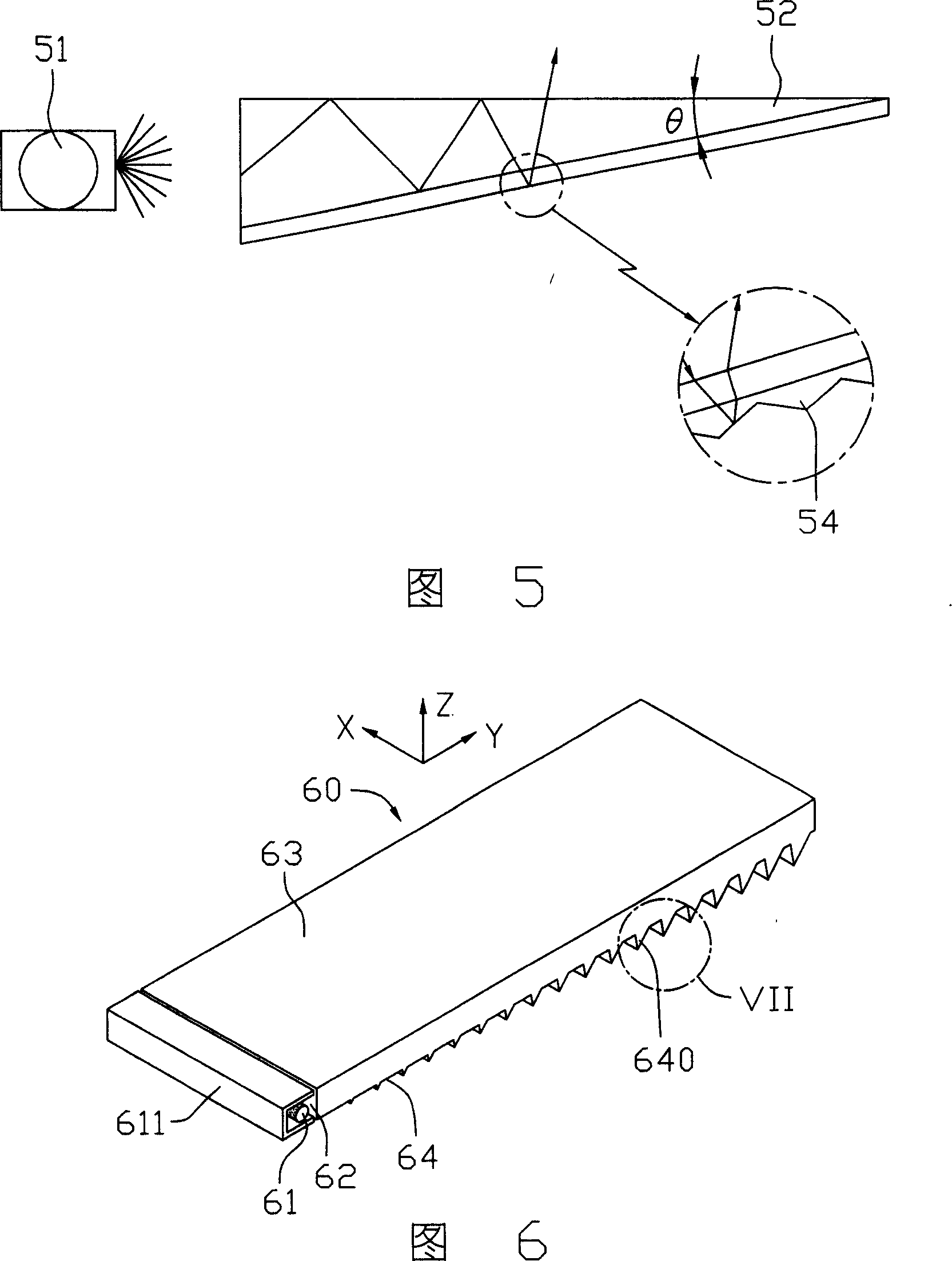
[0034] Please refer to FIG. 6 and FIG. 7 together. The first embodiment of the present invention provides a 14.1-inch flat light guide plate 60, including an incident surface 62, an outgoing surface 63, a reflective surface 64 opposite to the outgoing surface 63, and The other three sides (not labeled). Wherein, the incident surface 62 is formed on a side surface of the light guide plate 60 adjacent to the side cold cathode tube 61 . The emitting surface 63 is formed on the top surface of the light guide plate 60 . The reflective surface 64 is formed on the bottom surface of the light guide plate 60 . The reflective surface 64 is also formed with several V-shaped microstructures 640 protruding from the light guide plate 60 along the direction away from the outgoing surface 63 . The value ra...


PUM

PropertyMeasurementUnit
angleaaaaaaaaaa
angleaaaaaaaaaa
widthaaaaaaaaaa

Abstract

The present invention relates to a large-size light-conducting plate used in the liquid crystal display field and backlight module. Said light-conducting plate includes an incident face, an exit face and a reflecting face. Said invention also provides the concrete structure form with several V-type microstructures of said reflecting face, and makes the large-size light-conducting plate be combined with light source to implement the function of traditional backlight module with high luminance and good exiting light uniformity. Said invention also provides the backlight module using said light-conducting plate.

Description

【Technical field】 [0001] The invention relates to a light guide plate and a backlight module used in the field of liquid crystal display, in particular to a side-light large-size light guide plate and a backlight module. 【Background technique】 [0002] The Light Guide Plate (LGP) mainly includes a light incident surface, a reflective surface, an outgoing surface and several sides, and is an important part of a liquid crystal display backlight module. Its function is to guide the light emitted by scattered point light sources (such as light-emitting diodes) or line light sources (such as cold-cathode tubes) to exit from a plane, and at the same time improve the uniformity of the grayscale and brightness of the panel. The light guide plate is generally made of synthetic resin material, and its substrate shape is divided into flat plate type and wedge-shaped curved surface type. [0003] The light entering the light guide plate will propagate in the plate according to the prin...

Claims


Application Information

Patent Timeline
Patent Type & Authority Patents(China)
IPC IPC(8): G02F1/1335G02F1/133G02B5/02
CPCG02B6/0016G02B6/0038G02B6/0061
Inventor 冯迪严瑛白金国藩范守善
Owner TSINGHUA UNIV
Features
  • R&D
  • Intellectual Property
  • Life Sciences
  • Materials
  • Tech Scout
  • Unparalleled Data Quality
  • Higher Quality Content
  • 60% Fewer Hallucinations
Learn More