
Fluorescent powder color wheel base plate with demarcation structures and manufacturing method thereof

A fluorescent pink wheel and fluorescent powder technology, which is applied in the direction of optical elements, optics, and lighting device components used to change the spectral characteristics of emitted light. problem, to achieve the effect of improving accuracy

Inactive Publication Date: 2014-07-02
YANGZHOU G-NOVA OPTOELECTRONIC CO LTD
View PDF1 Cites 25 Cited by
  • Summary
  • Abstract
  • Description
  • Claims
  • Application Information

AI Technical Summary

Problems solved by technology

[0004] However, in the coating of the actual phosphor layer, especially the multi-color segment phosphor layer, due to the position, gap and shape of each fluorescent pink segment (such as width, thickness, flatness, angle, etc.), uniformity, etc. have high requirements, and the current manufacturing process, due to the limitations of materials, equipment, etc., it is difficult to accurately meet the above production requirements at the same time, resulting in fluorescent pink The overall light intensity of the wheel is reduced, and the chromaticity and color temperature are deviated.
[0005] We design and develop a fluorescent color wheel substrate that is easy to manufacture and has a good boundary structure, and use it to make phosphor powder sheet layers and fluorescent pink wheels, and finally Made into a light source using the phosphor sheet layer to solve the technical problems caused by the phosphor powder boundaries in the prior art with the excitation light of the LED light source and the laser light source

Method used


Image

  • Fluorescent powder color wheel base plate with demarcation structures and manufacturing method thereof
  • Fluorescent powder color wheel base plate with demarcation structures and manufacturing method thereof
  • Fluorescent powder color wheel base plate with demarcation structures and manufacturing method thereof

Examples


Embodiment 1

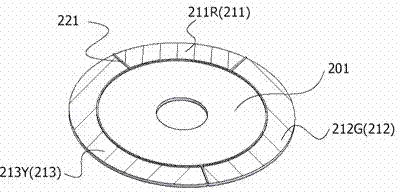
[0036] figure 1Shown is an embodiment of the present invention using a ring-shaped aluminum substrate with a silver-plated film on the surface, and a fluorescent powder layer with a boundary structure fluorescent pink segment boundary structure of the fluorescent pink wheel substrate. By extruding the circular substrate 201 with a diameter of 40 mm, it is separated into a structure with a demarcation effect, and the entire substrate is evenly divided into three independent regions 211 , 212 and 213 . As shown above, the boundary structure 221 is produced by mechanical and chemical methods such as extrusion on the substrate 201, and the width of the sag (ie, the protrusion of the boundary structure 221) in the corresponding phosphor sheet region of the substrate is 0.15mm. The boundary structure 221 The convex cross-section of the substrate is square, with a height of 0.2 mm. The lowest surface of the upper surface of the substrate when placed horizontally is used as a referenc...

Embodiment 2

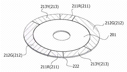
[0039] image 3 Shown is an embodiment of the present invention using a ring-shaped aluminum substrate with a silver-plated film on the surface, and a fluorescent powder layer with a boundary structure fluorescent pink segment boundary structure of the fluorescent pink wheel substrate. By extruding the circular substrate 201 with a diameter of 40 mm, it is separated into a structure with a demarcation effect, and the entire substrate 201 is evenly divided into six independent regions 211 , 212 and 213 and two symmetrical independent regions. As shown above, the boundary structure 222 is produced by mechanical and chemical methods such as extrusion on the substrate 201. The width of the protrusion (that is, the depression of the boundary structure 222) of the phosphor sheet area corresponding to the substrate is 0.2mm, and the boundary structure The concave cross-section of 222 is arc-shaped, with a height of -0.2mm, and the lowest surface of the upper surface of the substrate ...

Embodiment 3

[0042] Figure 5 Shown is an embodiment of the present invention using a ring-shaped aluminum substrate with a silver-plated film on the surface, and a fluorescent powder layer with a boundary structure fluorescent pink segment boundary structure of the fluorescent pink wheel substrate. By extruding the circular substrate 201 with a diameter of 40 mm, it is separated into a structure with a demarcation effect, and the entire substrate 201 is divided into two areas, one of which is concave. For reflective areas of the substrate (ie no machining and fluorescent pink segment coating). As shown above, the boundary structure 222 is produced by mechanical and chemical methods such as extruding the substrate. The concave width of the phosphor layer area corresponding to the substrate is 5 mm, and the concave cross section of the boundary structure 222 is square, and the height is - 0.18mm, taking the lowest surface of the upper surface of the substrate when it is placed horizontally...


PUM

PropertyMeasurementUnit
heightaaaaaaaaaa
heightaaaaaaaaaa
widthaaaaaaaaaa

Abstract

The invention relates to a fluorescent powder color wheel base plate with demarcation structures and a manufacturing method of the fluorescent powder color wheel base plate. The manufacturing method comprises the steps that firstly, the base plate is machined, the base plate generates certain deformation, demarcation is conducted, and the demarcation structures which are convex or concave relative to a datum plane are formed at the demarcation positions; meanwhile, protrusion layers which are in a required shape and have a certain height and width are formed in advance in required color section areas on the base plate through adhesives, and accurate demarcation and accurate control are conducted in the process of follow-up manufacturing of fluorescent powder color sections; then, multiple fluorescent powder color sections are manufactured through printing, adhesive dispensing, spaying and the like, and finally a needed multi-color-section fluorescent powder color wheel is manufactured. The fluorescent powder color wheel base plate with the demarcation structures has the advantages that the important parameters such as the relative positions, the required shape (the width, the thickness, the flatness, the angle, the gap and the like), and evenness of fluorescent powder sheet layers on the fluorescence powder color wheel base plate can be more accurately controlled, control over the demarcation of the fluorescent powder sheet layers is guaranteed, the requirement for the performance of the fluorescent powder sheet layers is met, and therefore the accuracy, the efficiency and the quality of the fluorescence powder sheet layers in the forming process are greatly improved.

Description

technical field [0001] The invention relates to the technical field of light sources for lighting and display, in particular to the structural design and manufacture of a substrate with a fluorescent pink wheel with a boundary structure. [0002] Background technique [0003] Now, more and more projectors choose to mainly use LED (light emitting Diode) or LD (laser diode) as the display light source. One of the modes is to directly use the multi-color excitation light source to emit light of different wavelengths such as red, green or blue. As a light source to achieve color display; the other is to use a red or green or blue as a light source, and then use it to excite and convert the other two primary colors, and finally realize color projection display by modulating the optical path. U.S. Patent No. 7,547,114B2 proposes a method for generating high-brightness time-sequential color light. The method collects and focuses the excitation light source on a phosphor powder t...

Claims


Application Information

Patent Timeline
Patent Type & Authority Applications(China)
IPC IPC(8): F21V9/10G03B21/20F21V9/40
Inventor 周际新钱向林杨生强周恒荣
Owner YANGZHOU G-NOVA OPTOELECTRONIC CO LTD
Learn More